
Nitride phosphor and method for manufacturing the same

a technology of phosphor and phosphor, which is applied in the field of nitride phosphor, can solve the problems of dramatic decrease in luminance, increase in phosphor temperature, and dramatic reduction in luminance, so as to improve internal quantum efficiency and external quantum efficiency, improve luminance and internal quantum efficiency, and improve luminance

Inactive Publication Date: 2014-09-04
MITSUBISHI CHEM CORP
View PDF0 Cites 8 Cited by
  • Summary
  • Abstract
  • Description
  • Claims
  • Application Information

AI Technical Summary

Benefits of technology

This patent describes how to make nitride phosphors that are brighter and more efficient at converting energy. The method of manufacturing these phosphors is also provided. This can be useful for improving the performance of lighting devices and other applications that use phosphors.

Problems solved by technology

However, one problem with YAG phosphors is that when used under a high power, there is a large so-called temperature extinction effect whereby raising the temperature of the phosphor lowers the luminance.
Another problem has been a dramatic decrease in luminance when excitation with light at about 350 to 420 nm is attempted in order to achieve an even better color reproducibility range and color rendering properties.

Method used


Image

  • Nitride phosphor and method for manufacturing the same
  • Nitride phosphor and method for manufacturing the same
  • Nitride phosphor and method for manufacturing the same

Examples


example 1

Preparation of Raw Materials

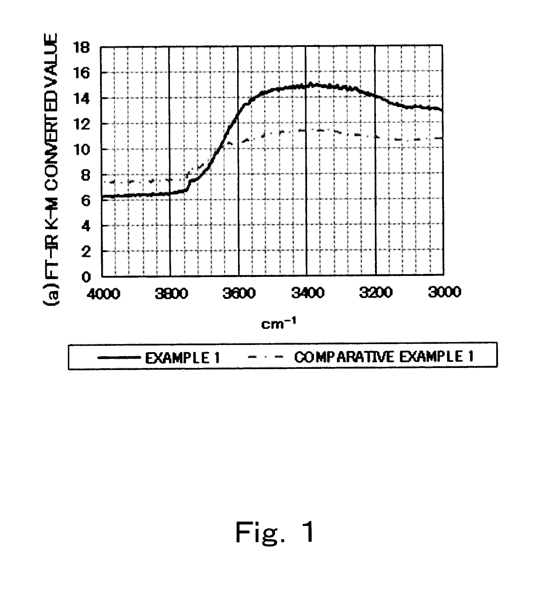
[0178]The alloy La:Si=1:1 (molar ratio), Si3N4 and CeF3 were weighed out such that La:Si=3:6 (molar ratio) and CeF3 / (alloy+Si3N4)=6 wt %. The weighed out raw materials were mixed together in a ball mill, then passed through a nylon mesh sieve, thereby preparing the raw materials. The operations from weighing out to preparation were carried out within a glove box having a nitrogen atmosphere with an oxygen concentration of 1% or less, and ball milling was carried out in a double vessel set out in open air that consisted of a nitrogen-sealed plastic pot within a similarly nitrogen-sealed closed vessel. Nylon-coated iron balls were used as the ball mill media (balls).

(Firing Step)

[0179]The prepared raw materials were charged into a Mo crucible and set within an electric furnace. The interior of the furnace was evacuated, following which the internal temperature was raised to 120° C. After confirming the interior pressure to be a vacuum, hydrogen-containing n...

example 2

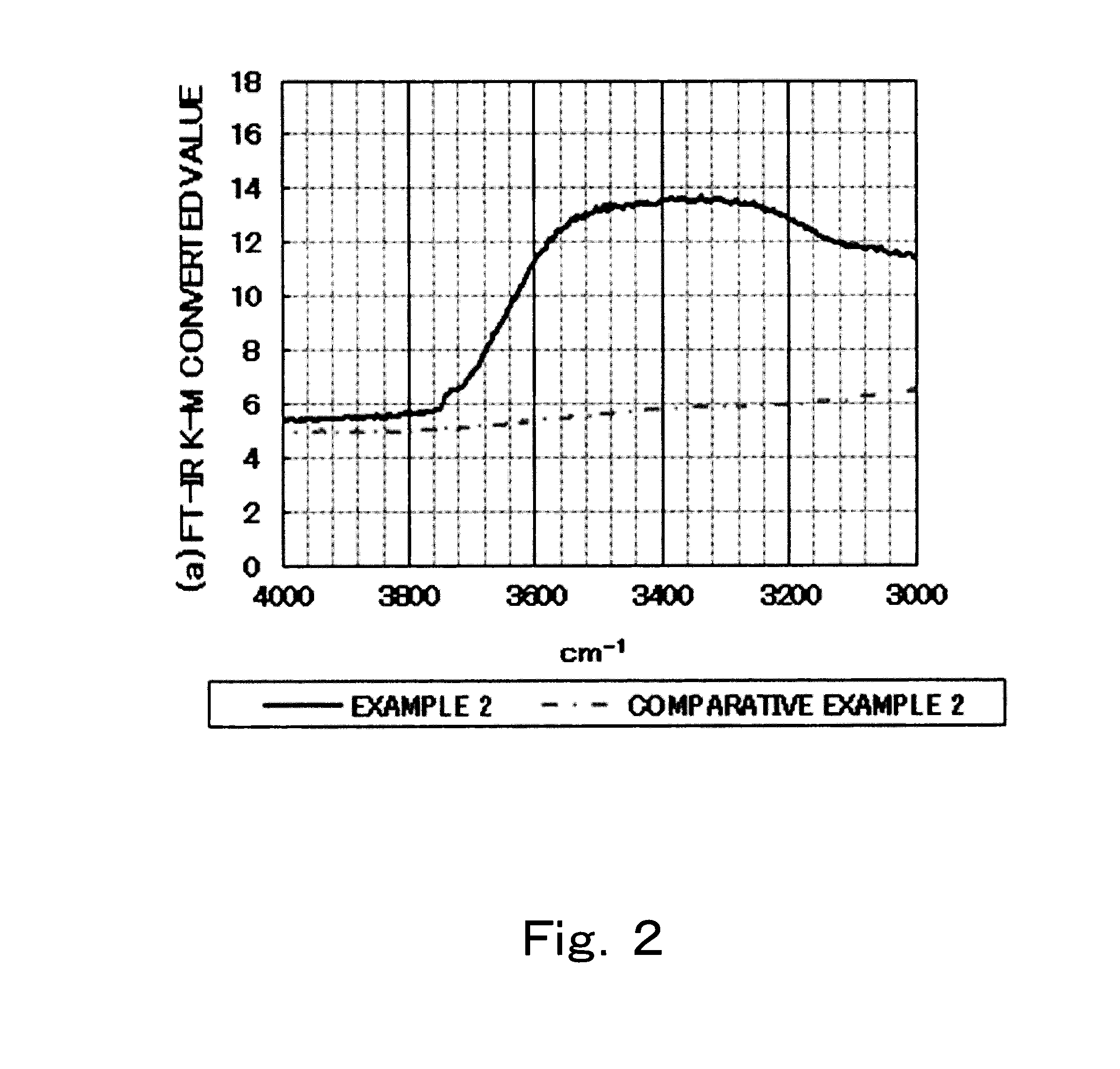
[0182]Aside from changing the length of time for which the fired phosphors are ground in the washing step so as to render the phosphors to the particle diameter shown in Table 1, Phosphors 2 were obtained in the same way as in Example 1. The color coordinates, luminance and particle diameter of the resulting phosphors are shown in Table 1. FIG. 2 shows the values obtained by converting the resulting infrared absorption spectrum to Kubelka-Munk function values.

example 3

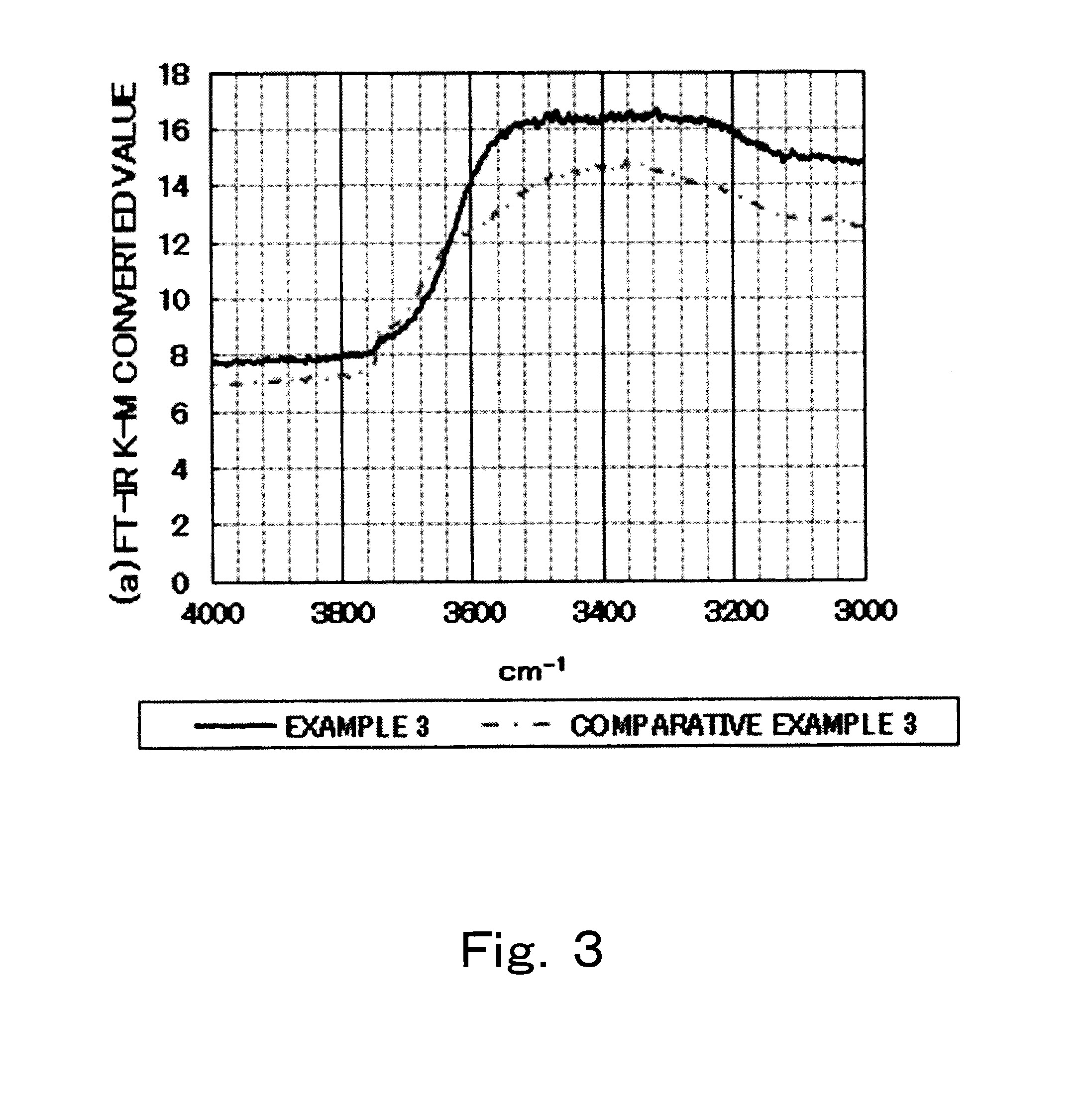
[0183]Aside from changing the media to zirconia balls during mixture within a ball mill when preparing the raw material and changing the length of time for which the fired phosphors are ground in the washing step so as to render the phosphors to the particle diameter shown in Table 1, Phosphors 3 were obtained in the same way as in Example 1. The color coordinates, luminance and particle diameter of the resulting phosphors are shown in Table 1. FIG. 3 shows the values obtained by converting the resulting infrared absorption spectrum to Kubelka-Munk function values.


PUM

PropertyMeasurementUnit
internal quantum efficiencyaaaaaaaaaa
infrared absorption spectrumaaaaaaaaaa

Abstract

Problem to be solved is to provide a nitride phosphor having enhanced luminance, internal quantum efficiency and external quantum efficiency compared to those of conventional nitride phosphors. The nitride phosphor is represented by the general formula (1) shown below and it is characterized in that the infrared spectroscopy measured by the diffuse reflection method at the measurement intervals of 2 cm−1 or lower, satisfies predetermined conditions:LnxSiyNn:Z  (1)(In the general formula (1), Ln represents rare earth element excluding the element to be used as an activator, Z represents an activator, x satisfies the condition of 2.7≦x≦3.3, y satisfies the condition of 5.4≦y≦6.6, and n satisfies the condition of 10≦n≦12.)

Description

CROSS-REFERENCE TO RELATED APPLICATION[0001]This is a continuation of International Application PCT / JP2012 / 079596, filed on Nov. 15, 2012, and designated the U.S., (and claims priority from Japanese Patent Application 2011-250153 which was filed on Nov. 15, 2011 and Japanese Patent Application 2011-250152 which was filed on Nov. 15, 2011) the entire contents of which are incorporated herein by reference.TECHNICAL FIELD[0002]This invention relates to a nitride phosphor. More specifically, the invention relates to a phosphor endowed with a luminance, internal quantum efficiency and external quantum efficiency which are all excellent.BACKGROUND ART[0003]In recent years, the trend toward energy conservation has led to a growth in demand for illumination and backlights that use LEDs. The LEDs used in such applications are white-emitting LEDs composed of phosphors placed on an LED chip that emits light of a blue or near-ultraviolet wavelength. It is common to use, as this type of white-em...

Claims


Application Information

Patent Timeline
Patent Type & Authority Applications(United States)
IPC IPC(8): C09K11/77
CPCC09K11/7766C09K11/0883
Inventor TAKASHINA, SHIHOOHTO, AKIHIROKIM, DOOHUN
Owner MITSUBISHI CHEM CORP
Learn More