
Reflective mask blank for EUV lithography and process for its production

a technology of euv lithography and reflective mask, applied in the field of euv lithography reflective mask blank, can solve the problems of inability to use a conventional dioptric system, the conventional photolithography method is close to its limit, and the miniaturization of semiconductor devices is being accelerated, so as to achieve maximum effect of heating treatment, film stress relaxation, and the effect of reducing the effect of aging

Active Publication Date: 2014-07-31
ASAHI GLASS CO LTD
View PDF4 Cites 50 Cited by
  • Summary
  • Abstract
  • Description
  • Claims
  • Application Information

AI Technical Summary

Benefits of technology

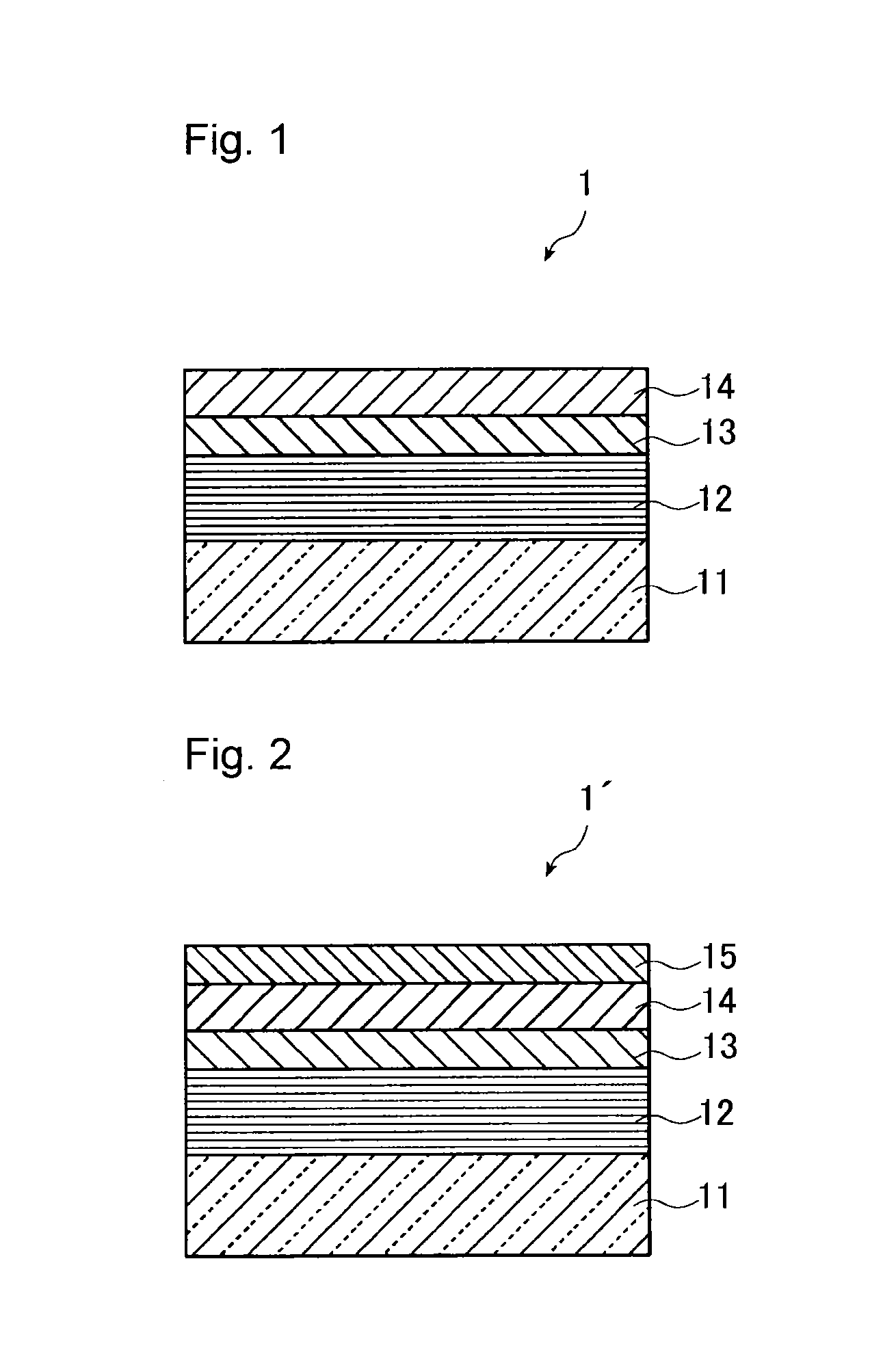
The present invention relates to a method for improving the performance of a multilayer reflective film used in extreme ultraviolet (EUV) lighting. The method involves heating the substrate on which the absorber layer is formed to prevent oxidation of the Si film which is the top layer of the multilayer reflective film during heating. The heat treatment reduces film stress and deformation of the substrate, resulting in improved performance. Additionally, the heat treatment relieves the change in film stress over time and reduces reflective properties degradation when exposed to EUV light. The use of a protective layer such as aRu film or compound film can further prevent oxidation of the film.

Problems solved by technology

However, the conventional photolithography method has come close to its limit, while miniaturization of semiconductor devices is being accelerated.
EUV light is likely to be absorbed by all kinds of substances, and the refractive index of substances at such a wavelength is close to 1, whereby it is not possible to use a conventional dioptric system like photolithography employing visible light or ultraviolet light.
However, along with a demand for a fine pattern, the slight deformation of a substrate (namely, the deformation of the substrate due to the application of the film stress) which was not considered as a problem in the past has become problematic.
For example, if a deformation larger than a specific size is present in the substrate for an EUV mask blank, specifically, in a case of a 152 mm×152 mm substrate which is usually used for producing an EUV mask blank, if the degree of warpage of the substrate exceeds 0.6 μm, the positioning accuracy of a pattern at the time of patterning the EUV mask blank may deteriorate.
Further, if warpage of such a degree results, at the time of transferring a pattern by using a reflective mask produced from the EUV mask blank, the mispositioning of the pattern or pattern defects may result.
Further, since light having a specific short wavelength range is used for an EUV lithography, the influence of the wavelength shift is large, and the shift of the peak wavelength of the reflectivity causes mismatch with a mirror of an exposure system used at the time of transferring a pattern.
As described above, the change with time of the stress of the multilayer reflective film causes various problems such that the flatness of a substrate is changed, when a mask is practically used.

Method used


Image

  • Reflective mask blank for EUV lithography and process for its production

Examples


example 1

Sample of Example 1

[0197]Surface: 0.217 μm

[0198]Rear surface: 0.237 μm

example 2

Sample of Example 2

[0199]Surface: 0.227 μm

[0200]Rear surface: 0.247 μm

Sample of Comparative Example 1

[0201]Surface: 0.195 μm

[0202]Rear surface: 0.192 μm

[0203]The degree of the difference in the flatness before and after the heating treatment shows how much the degree of warpage of a substrate 11 due to film stress is relaxed. It is evident from them that an effect to reduce the warpage of a substrate was improved by carrying out the heating treatment after forming an absorber layer.


PUM


Abstract

To provide a process for producing an EUV mask blank, whereby the deformation of a substrate due to film stress in a Mo / Si multilayer reflective film can be reduced, and the change with time of the film stress in the Mo / Si multilayer reflective film can be reduced.A process for producing a reflective mask blank for EUVL, which comprises forming a multilayer reflective film for reflecting EUV light on a film-forming surface of a substrate, then forming an absorber layer for absorbing EUV light, on the multilayer reflective film, to produce a reflective mask blank for EUV lithography, wherein the multilayer reflective film is a Mo / Si multilayer reflective film, the uppermost layer of the multilayer reflective film is a Si film, and after forming the absorber layer, the substrate on which the absorber layer is formed is subjected to heating treatment at a temperature of from 110 to 170° C.

Description

TECHNICAL FIELD[0001]The present invention relates to a reflective mask blank for EUV (Extreme Ultraviolet) lithography (hereinafter, in this specification, “reflective mask blank for EUV lithography” is referred to simply as “EUV mask blank”) to be used for the production of semiconductors, etc., and a process for its production.BACKGROUND ART[0002]Heretofore, in the semiconductor industry, a photolithography method employing visible light or ultraviolet light has been used as a technique to transfer a fine pattern required to form an integrated circuit with a fine pattern on e.g. a silicon substrate. However, the conventional photolithography method has come close to its limit, while miniaturization of semiconductor devices is being accelerated. In the case of the photolithography method, the resolution limit of a pattern is about ½ of the exposure wavelength. Even if an immersion method is employed, the resolution limit is said to be about ¼ of the exposure wavelength, and even i...

Claims


Application Information

Patent Timeline
IPC IPC(8): G03F1/22
CPCG03F1/22G03F1/24B82Y10/00B82Y40/00H01L21/0274
Inventor MAESHIGE, KAZUNOBUMIKAMI, MASAKI
Owner ASAHI GLASS CO LTD
Learn More