
Part for a timepiece movement

Active Publication Date: 2014-07-17
OMEGA SA
View PDF16 Cites 14 Cited by
  • Summary
  • Abstract
  • Description
  • Claims
  • Application Information

AI Technical Summary

Benefits of technology

The invention proposes a pivot pin with several technical effects. Firstly, it limits sensitivity to magnetic fields, which is beneficial for the horological industry where wear and shock resistance are crucial. Secondly, it is non-magnetic, meaning it is not affected by magnetic fields, which makes it more resistant to corrosion. Lastly, it is manufactured by a simple and economical process. In summary, the invention presents a pivot pin with low magnet sensitivity, high hardness, and excellent resistance to corrosion and wear.

Problems solved by technology

It will be noted that this rolling operation is very difficult or even impossible to achieve with materials having a low hardness, i.e. less than 600 HV.
Although this type of material provides satisfactory mechanical properties for the timepiece applications described above, it has the drawback of being magnetic and able to disrupt the working of a watch after being subjected to a magnetic field, particularly when the material is used to make a balance staff cooperating with a balance spring made of ferromagnetic material.
It should also be noted that these martensitic steels are also corrosion sensitive.
However, these austenitic steels have a crystallographic structure which means that they cannot be hardened or achieve hardnesses and thus wear resistances compatible with the requirements necessary for making timepiece pivot pins.
One means of increasing the hardness of these steels is cold working; however this hardening operation cannot achieve hardnesses of more than 500 HV.
Consequently, for parts which require high resistance to wear due to friction and pivots which have little or no risk of breakage or deformation, the use of this type of steel remains limited.
However, there have been observed significant risks of delamination of the hard layer and thus the formation of debris which can move around inside the watch movement and disrupt the operation of the timepiece, which is unsatisfactory.
However, these treatments are known to cause a significant loss of corrosion resistance because of the reaction of the nitrogen and / or carbon with the chromium in the steel and the formation of chromium nitride and / or chromium carbide causing localised depletion of the chromium matrix, which is detrimental to the desired timepiece application.

Method used


Image

  • Part for a timepiece movement
  • Part for a timepiece movement

Examples


Embodiment Construction

[0025]The invention relates to a part for a timepiece movement and particularly to a non-magnetic pivot pin for a mechanical timepiece movement.

[0026]The invention will be described below with reference to an application to a non-magnetic balance staff 1. Of course, other types of timepiece pivot pins may be envisaged such as, for example, timepiece wheel set arbours, typically escape pinions or pallet staffs.

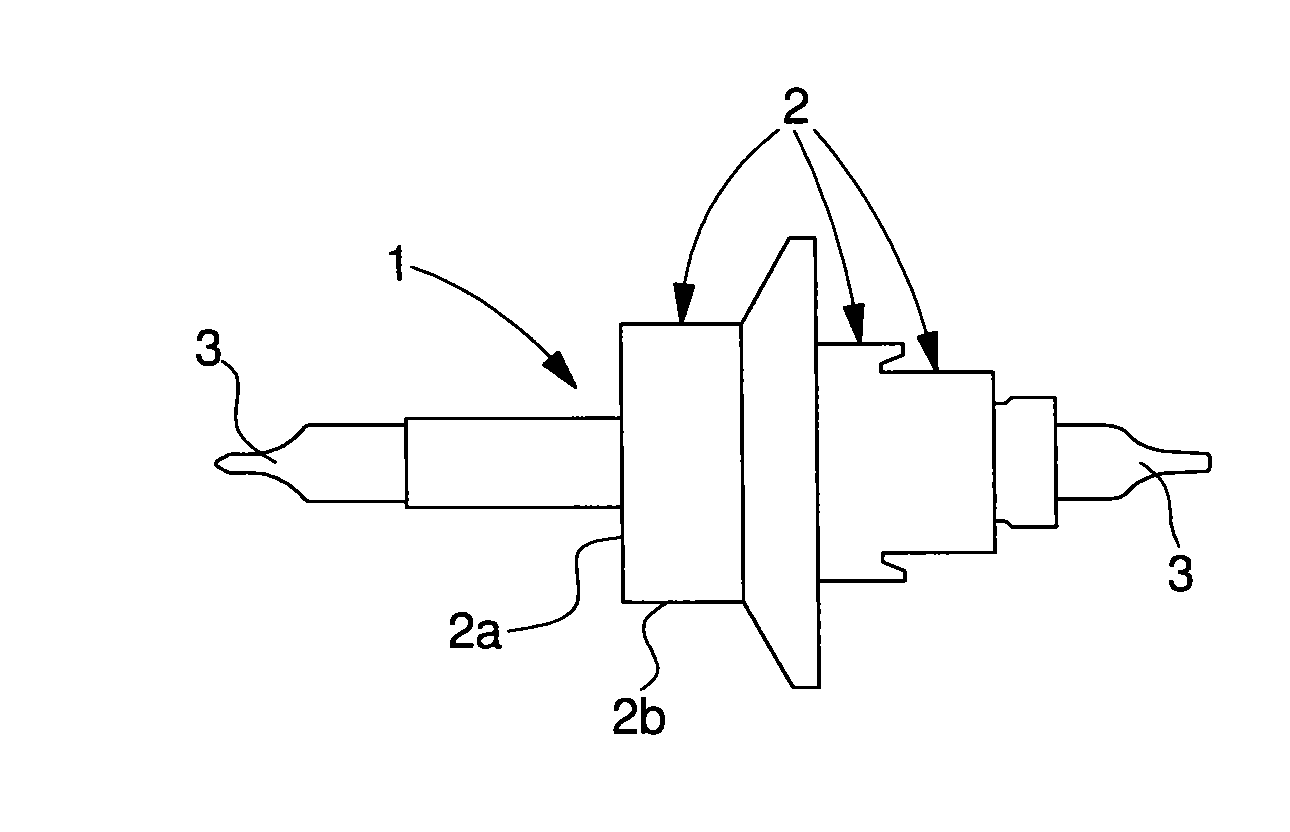
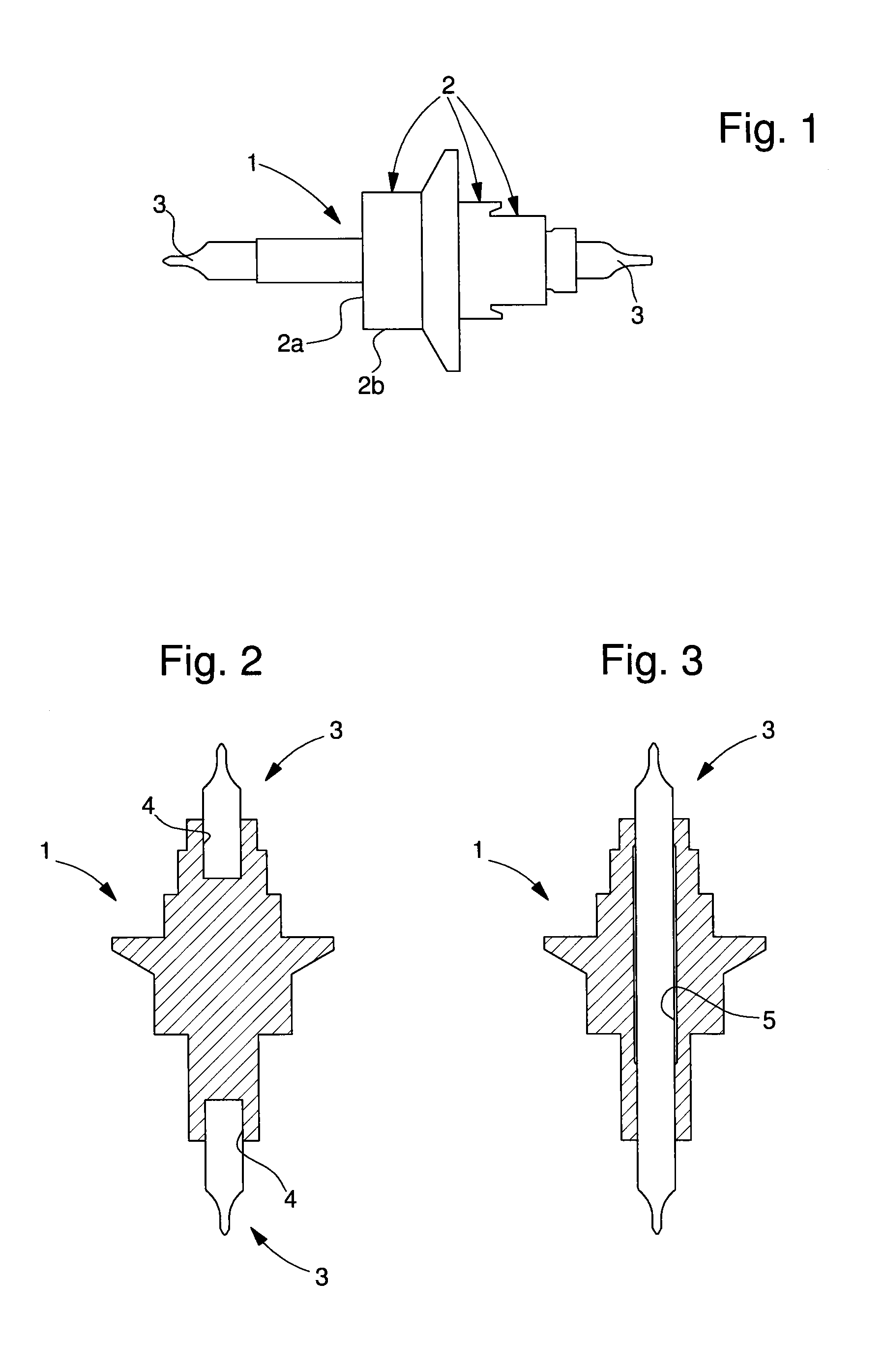
[0027]Referring to FIG. 1, there is shown a balance staff 1 according to the invention, which includes a plurality of sections 2 of different diameters conventionally defining shoulders 2a and projecting portions 2b arranged between two end portions defining pivots 3. These pivots are intended each to pivot in a bearing typically in an orifice in a jewel or ruby.

[0028]With the magnetism induced by objects that are encountered on a daily basis, it is important to limit the sensitivity of balance staff 1 to avoid affecting the working of the timepiece in which it is incorporated....


PUM


Abstract

The invention relates to a pivot pin for a timepiece movement including at least one pivot at at least one of the ends thereof, characterized in that said at least one pivot is formed of a composite material having a metallic matrix including at least one metal selected from among nickel, titanium, chromium, zirconium, silver, gold, platinum, silicon, molybdenum, aluminium or an alloy of the above metals, said matrix being charged with hard particles selected from among WC, TiC, TaC, TiN, TiCN, Al2O3, ZrO2, Cr2O3, SiC, MoSi2, Al N or a combination thereof, so as to limit the sensitivity of the pin to magnetic fields.The invention concerns the field of timepiece movements.

Description

[0001]This application claims priority from European Patent application No. 13151671.8 filed Jan. 17, 2013, the entire disclosure of which is hereby incorporated by reference.FIELD OF THE INVENTION[0002]The invention relates to a part for a timepiece movement and particularly to a non-magnetic pivot pin for a mechanical timepiece movement and more particularly to a non-magnetic escape pinion, balance staff and pallet staff.BACKGROUND OF THE INVENTION[0003]The manufacture of a pivot pin for a timepiece consists in performing bar turning operations on a hardenable steel bar to define various active surfaces (shoulder, projecting portion, pivots, etc.) and then in subjecting the bar-turned pin to heat treatments including at least one hardening operation to improve the hardness of the pin and one or more tempering operations to improve the roughness. The heat treatment operations are followed by an operation of rolling the pin pivots, which consists in polishing the pivots to the requi...

Claims


Application Information

Patent Timeline
IPC IPC(8): G04B15/14
CPCG04B15/14G04B1/16G04B17/32G04B13/02G04B17/063G04B43/007G04B13/022C22C29/00G04B1/04G04B43/00
Inventor VON GRUENIGEN, CEDRICCHARBON, CHRISTIANVERARDO, MARCO
Owner OMEGA SA
Learn More