Signal transmission device, receiving circuit, and electronic apparatus
- Summary
- Abstract
- Description
- Claims
- Application Information
AI Technical Summary
Benefits of technology
Problems solved by technology
Method used
Image
Examples
embodiment 1
Details of Millimeter-Wave Band Signal Transmission Function
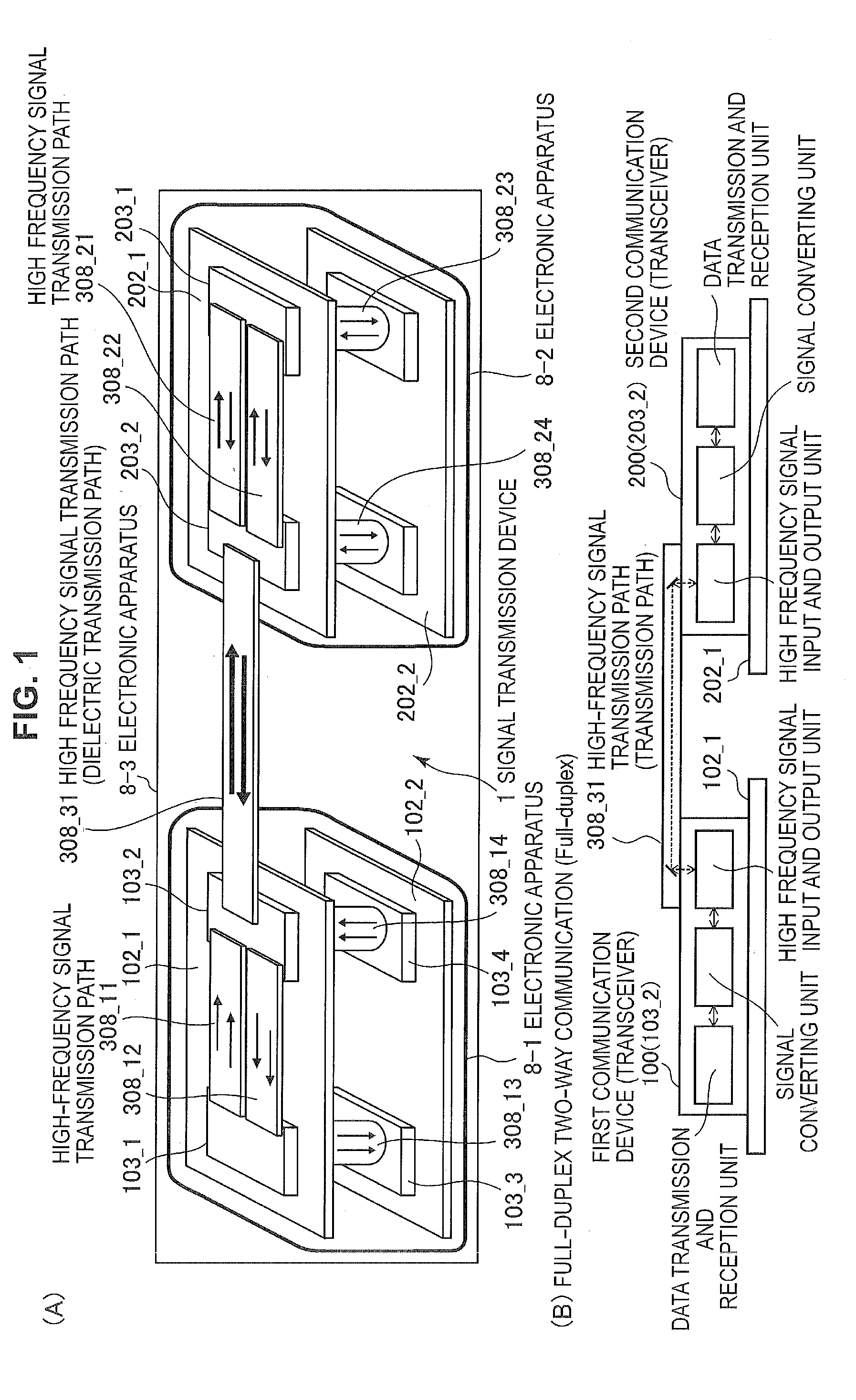
[0171]Embodiment 1 is an application example of a mutual interference countermeasure in a configuration corresponding to the full-duplex two-way communication. FIG. 11 is a diagram illustrating transmission and reception systems according to Embodiment 1, and is a functional block diagram of Embodiment 1, focusing on a signal transmission function from a modulation function unit to a demodulation function unit through the high frequency signal waveguide 308 (the signal transmission path 9). FIG. 11 illustrates a configuration corresponding to full-duplex two-way communication of a low frequency side (for example, a 57 GHz band and 12.5 gigabits per second (Gb / s)) and a high frequency side (for example, an 80 GHz band and 12.5 Gb / s).
[0172]In a signal transmission device 1(A) according to Embodiment 1, the first communication device 100 uses a carrier frequency of the high frequency side (80 GHz band) in a transmission proces...
embodiment 2
Details of Millimeter-Wave Signal Transmission Function
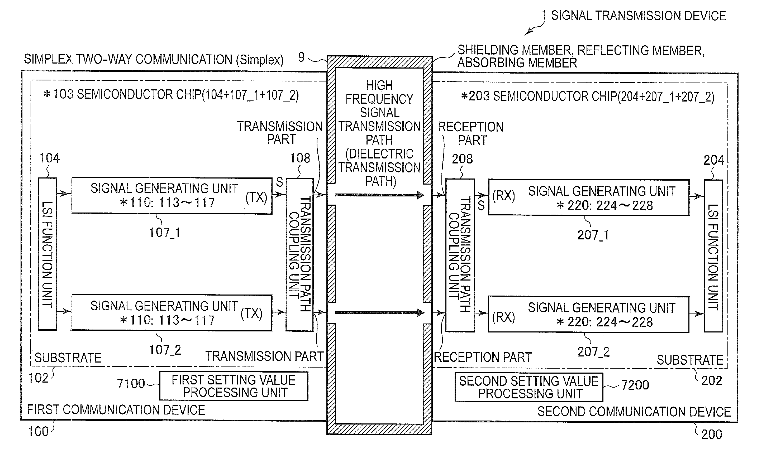
[0187]FIG. 13 is a diagram illustrating transmission and reception systems according to Embodiment 2 and is a functional block diagram according to Embodiment 2, focusing on a signal transmission function from a modulation function unit to a demodulation function unit through the high frequency signal waveguide 308 (the signal transmission path 9). FIG. 13 illustrates a configuration corresponding to the simplex two-way communication of a low frequency side (for example, a 57 GHz band and 12.5 Gb / s) and a high frequency side (for example, an 80 GHz band and 12.5 Gb / s). In addition, it is preferable to configure the transmission processing unit (a circuit composed of two amplifiers 4, and a peripheral circuit thereof) or the reception processing unit (a circuit composed of two low-noise amplifiers 400, and a peripheral circuit thereof) as a single chip.
[0188]Embodiment 2 is an application example of a mutual interference counterm...
embodiment 3
[0197]Embodiment 3 is an application example of a mutual interference countermeasure in a configuration when the full-duplex two-way communication and the simplex two-way communication are combined. Here, the most fundamental example including three channels will be described. Unlike Embodiment 4 to be described below, in the simplex two-way communication, it is assumed that a mutual interference countermeasure (that is, the method according to Embodiment 2) is unnecessary between transmission-sides and between reception-sides. That is, Embodiment 1 is applied when the full-duplex two-way communication is applied in a combination of two channels which are adjacent to each other. A leakage path of a simplex two-way communication system is not considered.
[0198]Hereinafter, in a relation of three channels, “Low” indicates a low frequency channel (57 GHz band). “Mid” indicates a mid frequency channel (80 GHz band). “High” indicates a high frequency channel (103 GHz band). When a desired...
PUM
 Abstract
Description
Claims
Application Information
 - R&D
- Intellectual Property
- Life Sciences
- Materials
- Tech Scout
- Unparalleled Data Quality
- Higher Quality Content
- 60% Fewer Hallucinations
Browse by: Latest US Patents, China's latest patents, Technical Efficacy Thesaurus, Application Domain, Technology Topic, Popular Technical Reports.
© 2025 PatSnap. All rights reserved.Legal|Privacy policy|Modern Slavery Act Transparency Statement|Sitemap|About US| Contact US: help@patsnap.com


