
Method and time-of-flight camera for providing distance information

a technology of distance information and time-of-flight camera, which is applied in the direction of distance measurement, instruments, and using reradiation, etc., can solve the problems of limited accuracy of tof cameras, restricted use of tof cameras, and problems such as high accuracy, to achieve the effect of improving the electromagnetic compliance of range finding devices, reducing spectral energy density, and high accuracy

Active Publication Date: 2014-06-12
SOFTKINETIC SENSORS
View PDF0 Cites 22 Cited by
  • Summary
  • Abstract
  • Description
  • Claims
  • Application Information

AI Technical Summary

Benefits of technology

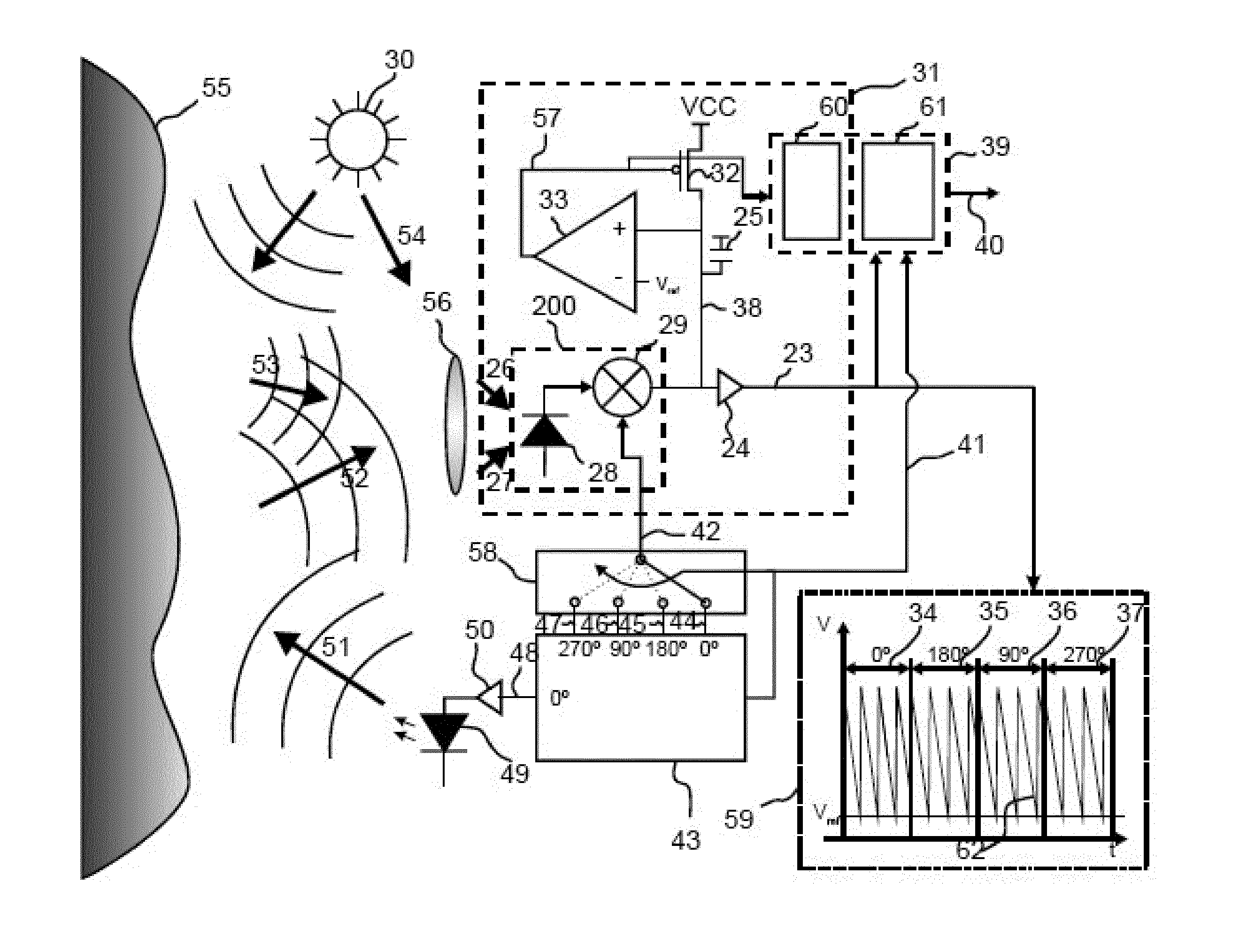
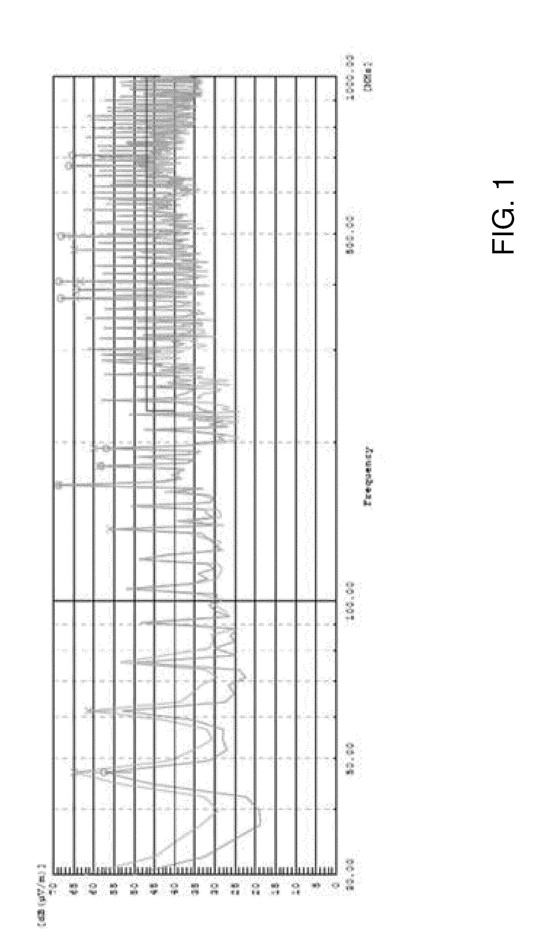
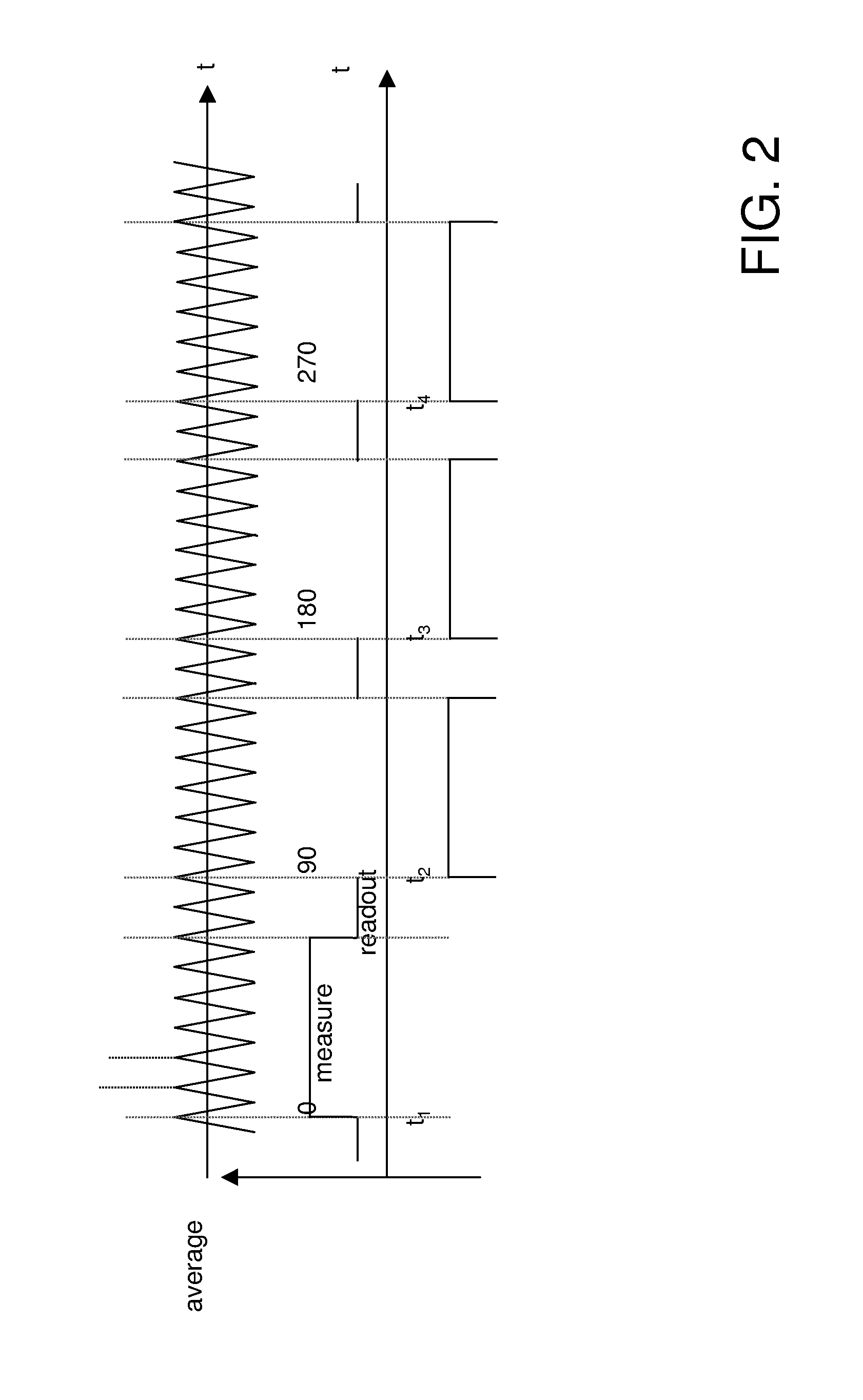
The present invention relates to a method and device for range finding using a time-of-flight sensor or camera. The invention has the advantage of obtaining high accuracy while reducing EMI. The method uses a periodic light signal with a low frequency perturbation, which improves EMC compliance without introducing jitter. The received reflections are easily evaluated by measuring the time delay or phase change between the emitted and received pulses. The invention also includes a method for integrating the received reflections over a duration to improve accuracy and coverage of a scene with distant and close-by objects. The invention ensures that the spectral content remains constant over the measurement period required for the acquisition of one distance determination. Overall, the invention provides a more efficient and reliable solution for range finding applications.

Problems solved by technology

Problems can arise, since TOF cameras must co-exist with other electronic devices.
Accordingly, the use of TOF cameras can be restricted and / or the accuracy of TOF cameras can be limited indirectly by the requirement to fulfill EMC requirements.
Reducing the amount of EMI radiated from an electronic device is one of the hardest problems to resolve in the drive for lower production costs.
Producing a compliant device can be quite costly if the necessary steps are not taken at design time.
Jitter will reduce the precision of range finding time-of flight devices in determining distance.

Method used


Image

  • Method and time-of-flight camera for providing distance information
  • Method and time-of-flight camera for providing distance information
  • Method and time-of-flight camera for providing distance information

Examples


Embodiment Construction

[0040]The present invention will be described with respect to particular embodiments and with reference to certain drawings but the invention is not limited thereto but only by the claims. The drawings described are only schematic and are non-limiting. In the drawings, the size of some of the elements may be exaggerated and not drawn on scale for illustrative purposes. Where an indefinite or definite article is used when referring to a singular noun e.g. “a” or “an”, “the”, this includes a plural of that noun unless something else is specifically stated. In the different figures, the same reference signs refer to the same or analogous elements. The illustrations in the figures are schematic.

[0041]The term “comprising”, used in the claims, should not be interpreted as being restricted to the means listed thereafter; it does not exclude other elements or steps. Thus, the scope of the expression “a device comprising means A and B” should not be limited to devices consisting only of com...


PUM


Abstract

The invention relates to a method for providing distance information of a scene with a time-of-flight camera (1), comprising the steps of emitting a modulated light pulse towards the scene, receiving reflections of the modulated light pulse from the scene, evaluating a time-of-flight information for the received reflections of the modulated light pulse, and deriving distance information from the time-of-flight information for the received reflections, whereby a spread spectrum signal is applied to a base frequency of the modulation of the light pulse, and the time-of-flight information is evaluated under consideration of the a spread spectrum signal applied to the base frequency of the modulation of the light pulse. The invention further relates to a time-of-flight camera (1) for providing distance information from a scene, whereby the time-of-flight camera (1) performs the above method.

Description

[0001]The present invention relates to a method for providing distance information of a scene with a range finding device such as a time-of-flight sensor or time-of-flight camera, comprising the steps of emitting a modulated light pulse towards the scene, receiving reflections of the modulated light pulse from the scene, evaluating a time-of-flight information for the received reflections of the modulated light pulse, and deriving distance information from the time-of-flight information for the received reflections. The present invention also relates to a range finding device such as a time-of-flight sensor or time-of-flight camera for providing distance information from a scene according to the above method.BACKGROUND[0002]A time-of-flight camera, also referred to as TOF camera, is a camera that usually comprises a light source or emitter unit for emitting modulated light pulses, a receiver unit that captures reflections of the light pulses, an evaluation unit, which evaluates time...

Claims


Application Information

Patent Timeline
IPC IPC(8): G01S17/10G01S7/4865G05D13/08
CPCG01S17/10G01S7/484G05D13/08H04B15/00G01S7/4865G01S7/487
Inventor VAN DER TEMPEL, WARDGROOTJANS, RIEMER
Owner SOFTKINETIC SENSORS
Learn More