
Methods and Devices for Fluid Driven Adult Devices

a technology for adult devices and fluids, applied in the direction of machines/engines, liquid fuel engines, positive displacement liquid engines, etc., can solve the problems of more batteries, complicated design, and vibration of motors

Active Publication Date: 2014-03-27
OBOTICS INC
View PDF9 Cites 26 Cited by
  • Summary
  • Abstract
  • Description
  • Claims
  • Application Information

AI Technical Summary

Benefits of technology

The present invention provides improved devices for sexual pleasure that use fluidic control with vibration and non-vibration functions. The invention includes a fluidic control system with a pump and control circuit, as well as at least one fluidic actuator and at least one valve that work together to control fluid flow. The invention also includes a method for customizing the device to an individual's preferences by programming the device with a set-up procedure, automatically varying an aspect of the device's function until the individual provides input, and storing the individual's input within a profile for future reference. Overall, the invention offers enhanced functionality and customization options for devices used for sexual pleasure.

Problems solved by technology

Vibrators typically operate through the operation of an electric motor wherein a small weight attached off-axis to the motor results in vibration of the motor and hence the body of the portion of the vibrator coupled to the electric motor.
More batteries consume more space within devices which are generally within a relatively narrow range of physical sizes approximating that of the average penis in penetrative length and have an external portion easily gripped by the user thereby complicating the design.
Typically, toys that are large due to power requirements are not as successful as more compact toys.
However, such electric motors with off-axis weights cannot easily operate at low frequencies when seeking to induce excitation to the user in a manner that mimics physical intercourse and stimulation where for example stimulation would be very low or low frequency and high or very high amplitude.
Such low frequency, high amplitude vibrations are desirable to users but are not achieved with the vibrators of the prior art.
For example providing operation below 40 Hz, below 10 Hz, below 4 Hz, below 1 Hz cannot be provided where small DC motors cannot produce much torque at low revolutions per minute (RPM) and therefore cannot move the large heavy weight to produce high amplitude variations.
However, others have not been commercially successful to date including, for example, the use of linear screw drive mechanisms to provide devices that adjust in length.
Dildo is the common name used to define a phallus-like sex toy, which does not, however, provide any type of vibrations.
Due to its small dimension, it is typically powered by a single battery and usually has limited controls; some may have only one speed.
However, to date the commercial deployment of sex toys exploiting fluidics has been limited to the provisioning of lubricating oils or gels during use of the device to reduce friction and subsequent pain / irritation either through extended use of the device or from low natural lubrication of the user upon whom the device is used.
When considering users of the prior art devices described above these present several limitations and drawbacks in terms of providing enhanced functionality, dynamic device adaptability during use, and user specific configuration for example.
As noted supra, the commercial deployment of devices exploiting fluidics has been limited to lubricant release during device use despite several prior art references to using fluidics including, for example, those described below.
The system taught is bulky and complex requiring set-up through needle valves to set the volumes of air adjusted within the massaging sleeve during the suction and injection phases.
However, Kain does not teach the use of such motion for stimulation purposes but rather to allow for adjustment of that end of the device to accommodate different users allowing, for example, insertion, inflation and hence retention of that device end.
However, Gil teaches that vibratory action of the device is provided by a conventional electric motor with off-axis weight.
It is evident therefore to one skilled in the art that the hydraulic driven devices as taught by Faulkner, Gil, Kain, Levy, Schroeder, and Stoughton do not provide devices with the desirable and beneficial features described above which are lacking within known devices of the conventional mechanical activation with electrical motors.
However, to date as discussed supra hydraulic devices have not been developed or commercially deployed despite the prior art fluidic concepts identified above in respect of fluidic devices and these prior art pumps.
This is likely due to the fact that fluidic pumps are bulky, have low efficiency, and do not operate in the modes required for such devices, such as, for example, low frequency, variable duration, and pulsed for those providing primary pumps for dimensional adjustments or for example high frequency operation for those providing secondary pumps for vibration and other types of motion / excitation.
For example, a conventional rotary pump offers poor pressure at low revolutions per minute (rpm), has a complicated motor and separate pump, multiple moving parts, relatively large and expensive even with small impeller, and low effective flow rate from a small impeller.
Solenoids whilst offering larger force than voice coil motors have a poor ability to exert a steady force on a long stroke piston, typically a few millimeters, and where constant force solenoids are implemented these tend to be short stroke with increased complexity in the design of the coil, body and shape of the cross-section of the plunger.
However, such actuators are primarily designed for long stroke, large load displacement, and as replacements for pneumatic cylinders.
Accordingly, the resulting magnet is complicated and expensive and whilst Ibrahim in “T.

Method used


Image

  • Methods and Devices for Fluid Driven Adult Devices
  • Methods and Devices for Fluid Driven Adult Devices
  • Methods and Devices for Fluid Driven Adult Devices

Examples


Embodiment Construction

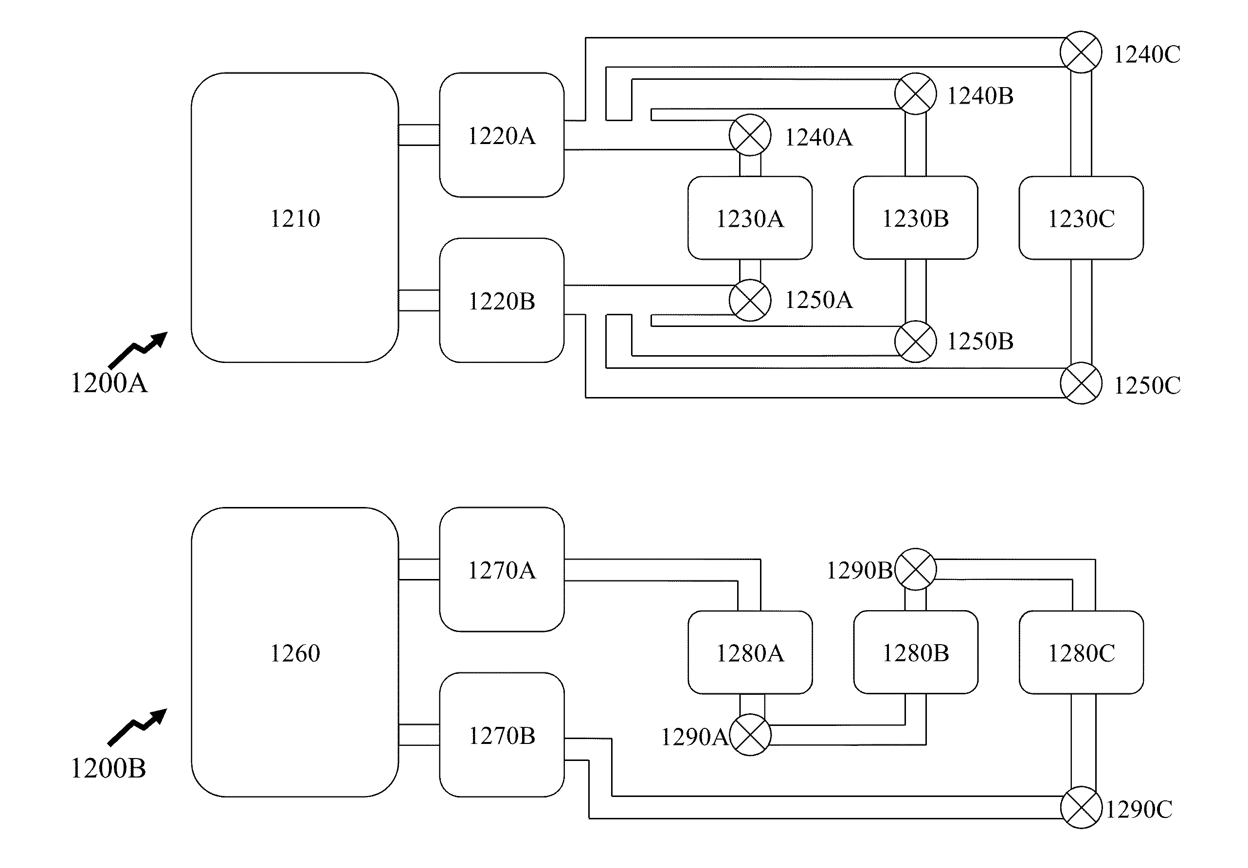
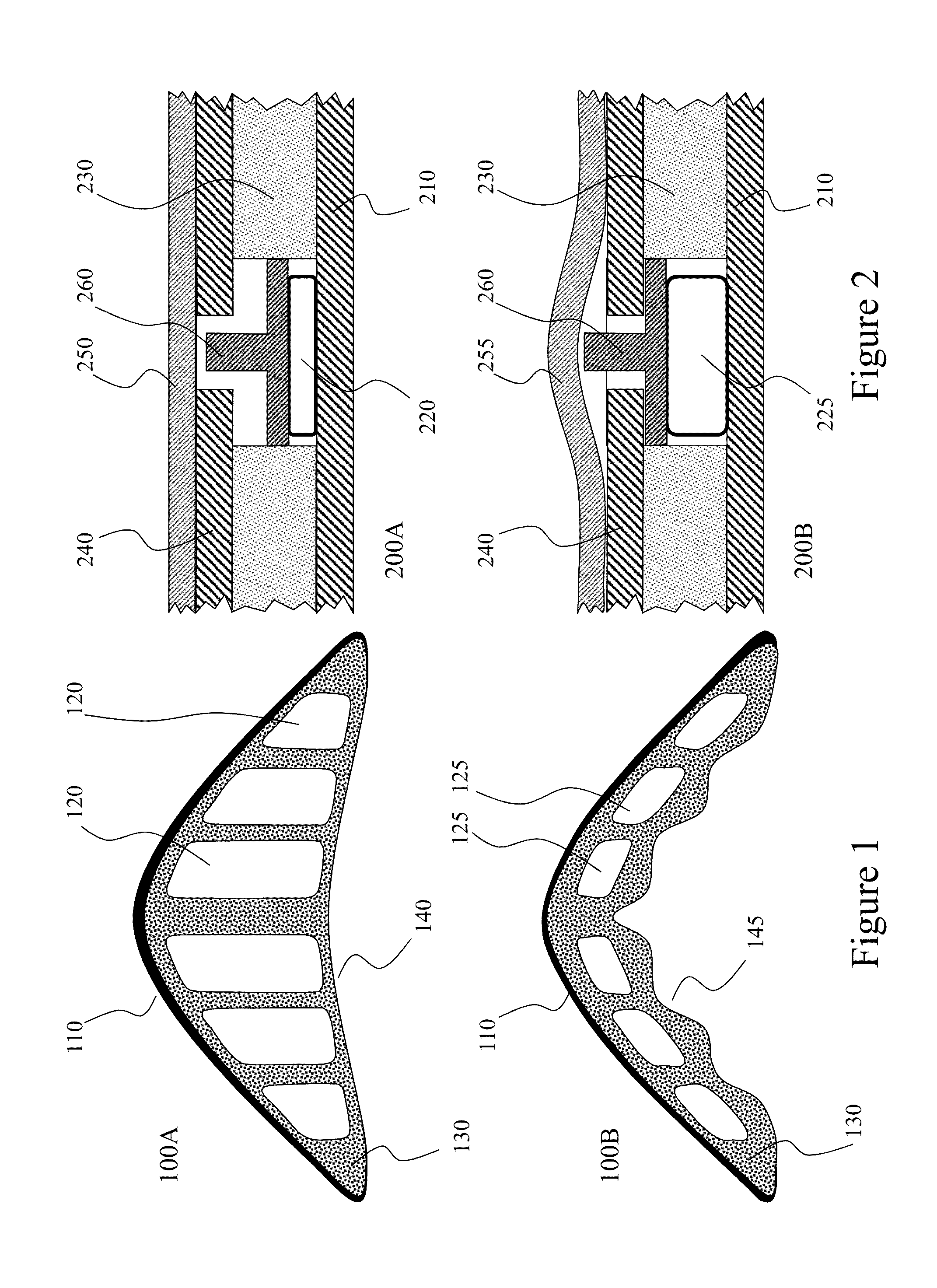
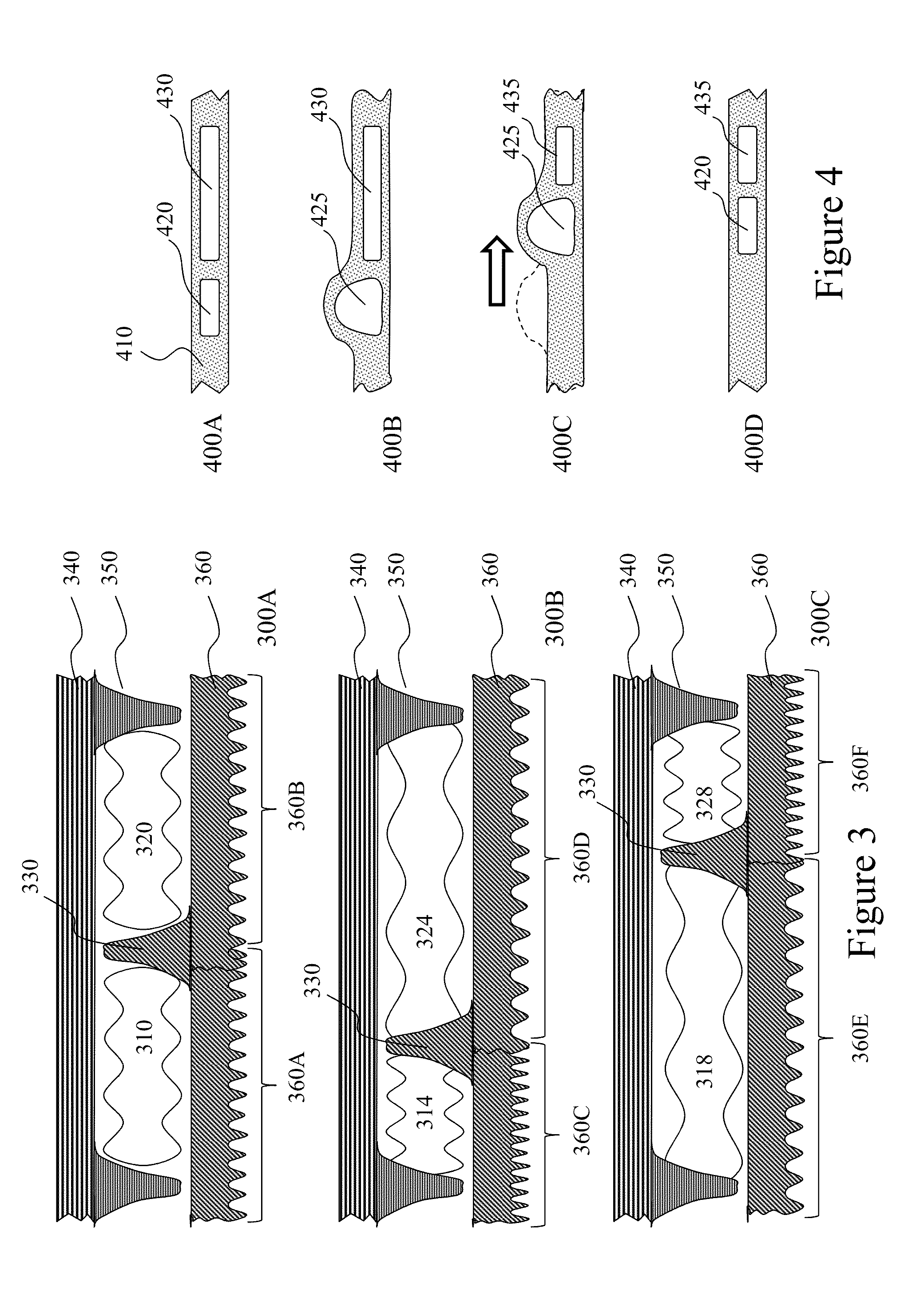
[0138]The present invention is directed to devices for sexual pleasure and more particularly to devices exploiting fluidic control with vibratory and non-vibratory function and movement.

[0139]The ensuing description provides representative embodiment(s) only, and is not intended to limit the scope, applicability or configuration of the disclosure. Rather, the ensuing description of the embodiment(s) will provide those skilled in the art with an enabling description for implementing an embodiment or embodiments of the invention. It being understood that various changes can be made in the function and arrangement of elements without departing from the spirit and scope as set forth in the appended claims. Accordingly, an embodiment is an example or implementation of the inventions and not the sole implementation. Various appearances of “one embodiment,”“an embodiment” or “some embodiments” do not necessarily all refer to the same embodiments. Although various features of the invention ...


PUM

PropertyMeasurementUnit
Pressureaaaaaaaaaa
Frequencyaaaaaaaaaa
Material propertiesaaaaaaaaaa

Abstract

A device for use by an individual for sexual pleasure varying in form, i.e. shape, during its use and allowing for the user to select multiple variations of form either discretely or in combination and for these dynamic variations to be controllable simultaneously and interchangeably while being transparent to the normal use of the device, including the ability to insert, withdraw, rotate, and actuate the variable features manually or remotely. According to embodiments of the invention localized and global variations of devices are implemented using fluidics and electromagnetic pumps / valves wherein a fluid is employed such that controlling the pressure of the fluid results in the movement of an element within the device or the expansion / contraction of an element within the device.

Description

CROSS-REFERENCE TO RELATED APPLICATIONS[0001]This patent application claims the benefit of U.S. Provisional Patent Application 61 / 705,809 filed on Sep. 26, 2012 entitled “Methods and Devices for Fluid Driven Adult Devices.”FIELD OF THE INVENTION[0002]The present invention relates to devices for sexual pleasure and more particularly to devices exploiting fluidic control in conjunction with vibratory and non-vibratory function and movement.BACKGROUND OF THE INVENTION[0003]The sexual revolution, also known as a time of “sexual liberation”, was a social movement that challenged traditional codes of behavior related to sexuality and interpersonal relationships throughout the Western world from the 1890s to the 1980s. However, its roots may be traced back further to the Enlightenment and the Victorian era in the Western world and even further in the Eastern world. Sexual liberation included increased acceptance of sex outside of traditional heterosexual, monogamous relationships (primaril...

Claims


Application Information

Patent Timeline
IPC IPC(8): A61H19/00A61H9/00A61H23/00
CPCA61H19/40A61H9/0078A61H9/0057A61H23/00F04B3/00F04B11/0008F04B11/0033F04B11/0091F04B17/04F04B17/044F04B53/10F04B53/18A61H2201/0153A61H23/04A61H2201/1238A61H2201/1409A61H23/0218A61H23/0263A61H2201/1246A61H2201/5002A61H2201/5064A61H2201/5071A61H19/32Y10T137/85978A41B9/04A41C1/14A41C5/005A61H2201/1645A61H2201/165
Inventor MURISON, BRUCE
Owner OBOTICS INC
Learn More