
Insulated wire and coil using the same

a technology of insulated wire and coil, which is applied in the direction of plastic/resin/waxes insulators, transportation and packaging, synthetic resin layered products, etc., can solve the problems of mechanical strength decline, and achieve high pdiv, high temperature processability, and excellent partial discharge resistance.

Active Publication Date: 2014-03-06
HITACHI METALS LTD
View PDF5 Cites 3 Cited by
  • Summary
  • Abstract
  • Description
  • Claims
  • Application Information

AI Technical Summary

Benefits of technology

The present invention describes an insulated wire with excellent resistance to partial discharge and high temperature processing. The insulation layer is made of a specific polyimide mixture containing two acid components, and has a high storage elastic modulus at high temperatures. The insulated wire can be used to make a coil with good performance. The conductor can be a metal wire such as copper or aluminum wire.

Problems solved by technology

However, reducing the imide group in the polyimide may cause a decrease in mechanical strength.

Method used


Image

  • Insulated wire and coil using the same
  • Insulated wire and coil using the same
  • Insulated wire and coil using the same

Examples


embodiment

[0027]The embodiment of an insulated wire and a coil using the same according to the invention will be described in detail below.

[0028]Insulated Wire

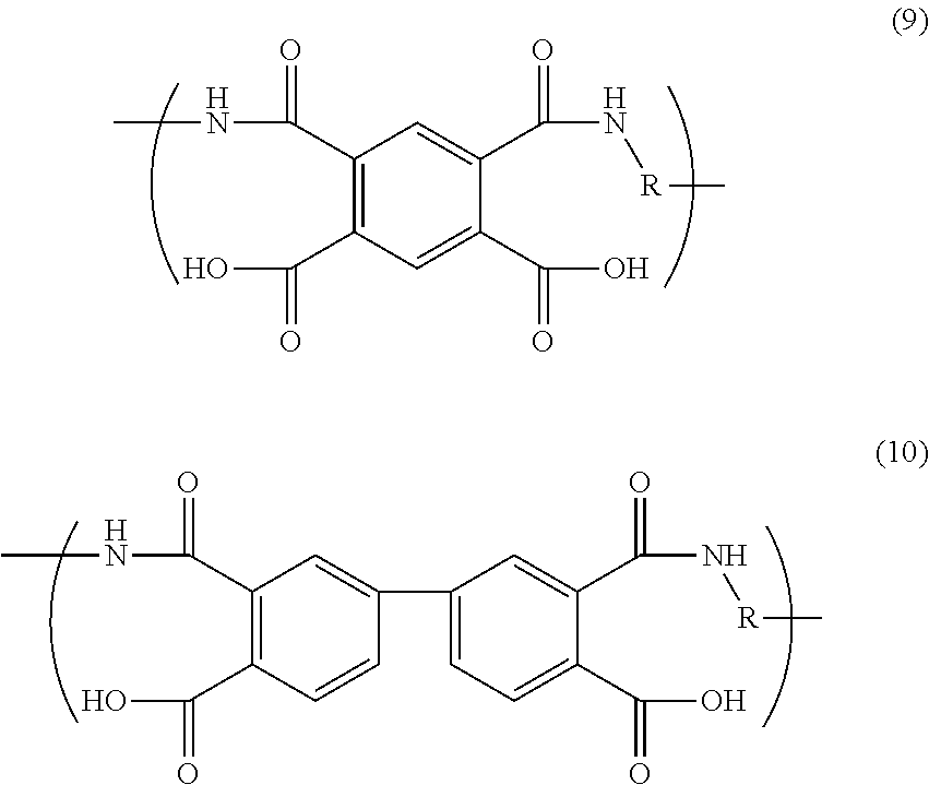
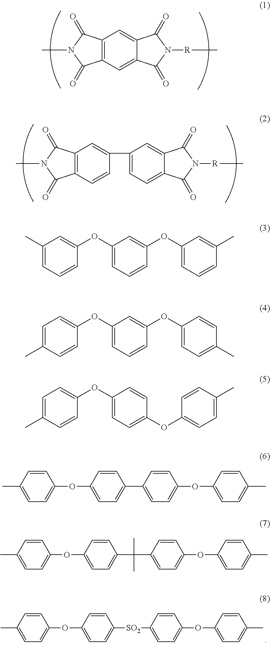
[0029]The insulated wire in the present embodiment is an insulated wire provided with a conductor and a polyimide insulation layer provided on an outer periphery of the conductor, and is configured such that the insulation layer is formed of a polyimide having a repeating unit represented by the formula (1) and a repeating unit represented by the formula (2), a first acid component in the repeating unit represented by the formula (1) and a second acid component in the repeating unit represented by the formula (2) are mixed in a molar ratio range of 85:15 to 40:60 as expressed by a molar ratio (the first acid component:the second acid component), R representing a residue of a diamine component in the formulas (1) and (2) is composed of a residue of 4,4′-diaminodiphenyl ether and a residue of a diamine selected from a group of diamines re...

example 1

[0052]After dissolving 4,4′-diaminodiphenyl ether (ODA) and 4,4′-bis(4-aminophenoxy)biphenyl (BAPB) into N-methylpyrrolidone (NMP), pyromellitic dianhydride (PMDA) and 3,3′,4,4′-biphenyltetracarboxylic dianhydride (s-BPDA) were dissolved therein and the mixture was stirred at room temperature for 12 hours, thereby obtaining a polyamic acid coating material having a mixture ratio of “PMDA:s-BPDA:ODA:BAPB=75:25:85:15”. Dilution of the polyamic acid coating material was adjusted for coating workability. Using a conventional means, the obtained coating material was applied to a 0.8 mm-diameter copper wire and baked in a coating oven at 450° C. for 90 seconds. This was repeated fifteen times, thereby obtaining an insulated wire having a film thickness of 40 μm.

example 2

[0053]Example 2 was the same as Example 1, except that the mixture ratio for the polyamic acid coating material was changed to “PMDA:s-BPDA:ODA:BAPB=50:50:50:50”.


PUM

PropertyMeasurementUnit
Temperatureaaaaaaaaaa
Pressureaaaaaaaaaa

Abstract

An insulated wire includes a conductor, and a polyimide insulation layer formed on an outer periphery of the conductor. The insulation layer includes a polyimide including a repeating unit represented by formula (1) and a repeating unit represented by formula (2). A first acid component in the repeating unit represented by the formula (1) and a second acid component in the repeating unit represented by the formula (2) are mixed in a molar ratio range of 85:15 to 40:60 as expressed by a molar ratio (the first acid component:the second acid component). R as a residue of a diamine component in the formulas (1) and (2) includes a residue of 4,4′-diaminodiphenyl ether and a residue of one selected from a group of diamines represented by the formulas (3) to (8). A storage elastic modulus of the polyimide at 325° C. is not less than 50 MPa.

Description

[0001]The present application is based on Japanese patent application No. 2012-193046 filed on Sep. 3, 2012, the entire contents of which are incorporated herein by reference.BACKGROUND OF THE INVENTION[0002]1. Field of the Invention[0003]The invention relates to an insulated wire and a coil using the same. In more detail, the invention relates to an insulated wire excellent in partial discharge resistance and high temperature processability, and a coil using the same.[0004]2. Description of the Related Art[0005]An insulated wire having an insulation layer (an insulating film) excellent in mechanical characteristics, heat resistance and solvent resistance has been proposed in which a polyimide synthesized from, e.g., pyromellitic dianhydride (PMDA) and 4,4′-diaminodiphenyl ether (ODA) is used for the insulation layer (see, e.g., JP-A 9-106712).[0006]In recent years, industrial motors have been reduced in size and weight. In addition, inverter drive for improving dynamic performance,...

Claims


Application Information

Patent Timeline
IPC IPC(8): H01B3/30
CPCH01B3/306Y10T428/2969
Inventor USHIWATA, TAKAMIHONDA, YUKINABESHIMA, SHUTAKIKUCHI, HIDEYUKI
Owner HITACHI METALS LTD
Learn More