
Fastening device for a line and method for fastening a line

a technology of fastening device and line, which is applied in the direction of metal working apparatus, manufacturing tools, transportation and packaging, etc., can solve the problems of increasing the cost of fastening, and increasing the cost of the overall cost of the line, so as to achieve at least partially reduce the disadvantages of conventional sleeves and fastening devices

Inactive Publication Date: 2014-03-06
ROBERT BOSCH GMBH
View PDF65 Cites 10 Cited by
  • Summary
  • Abstract
  • Description
  • Claims
  • Application Information

AI Technical Summary

Benefits of technology

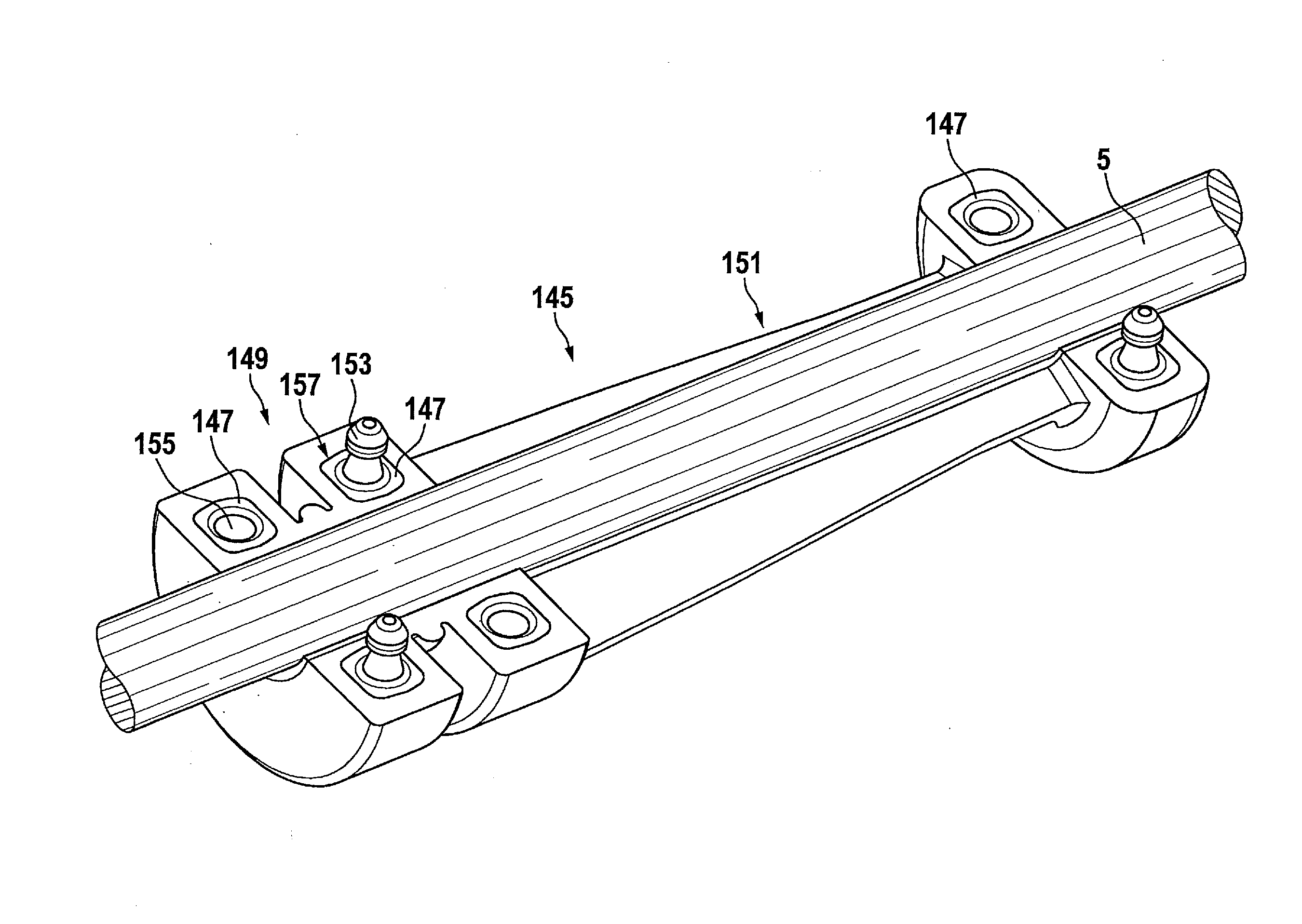
This patent is about a sleeve used in a subassembly. The patent explains how the sleeve can be made using a simplified installation method, either by form-locked clipping or by connecting the different parts using glue, heat-sealing, or joining. The sleeve is made of a thermoplastic elastomer, which allows for cost-effective manufacturing and flexibility. In some cases, the sleeve subareas may need to be rigid, so nonelastic materials can be used. The sleeve subareas can be manufactured using injection molding, which allows for flexible design and cost-effective manufacture. The sleeve may also be made by connecting two identical halves, which simplifies the manufacturing process. The technical effects of this patent are a simplified installation method and a more cost-effective and reliable design for a sleeve.

Problems solved by technology

However, in this fastening method the line or the cable must have a free end; i.e., plugs, for example, must not have been installed beforehand on the cable.
Furthermore, the spreading of the sleeve which is necessary for fastening may entail an additional expenditure of effort.
The quantity of material needed for the sleeve may be considerable, and may contribute to the overall costs in fastening the line.
However, expensive tools must be provided for the injection molding process, so that the costs of molding on the sleeve may contribute significantly to the overall costs of the fastening method.

Method used


Image

  • Fastening device for a line and method for fastening a line
  • Fastening device for a line and method for fastening a line
  • Fastening device for a line and method for fastening a line

Examples


Embodiment Construction

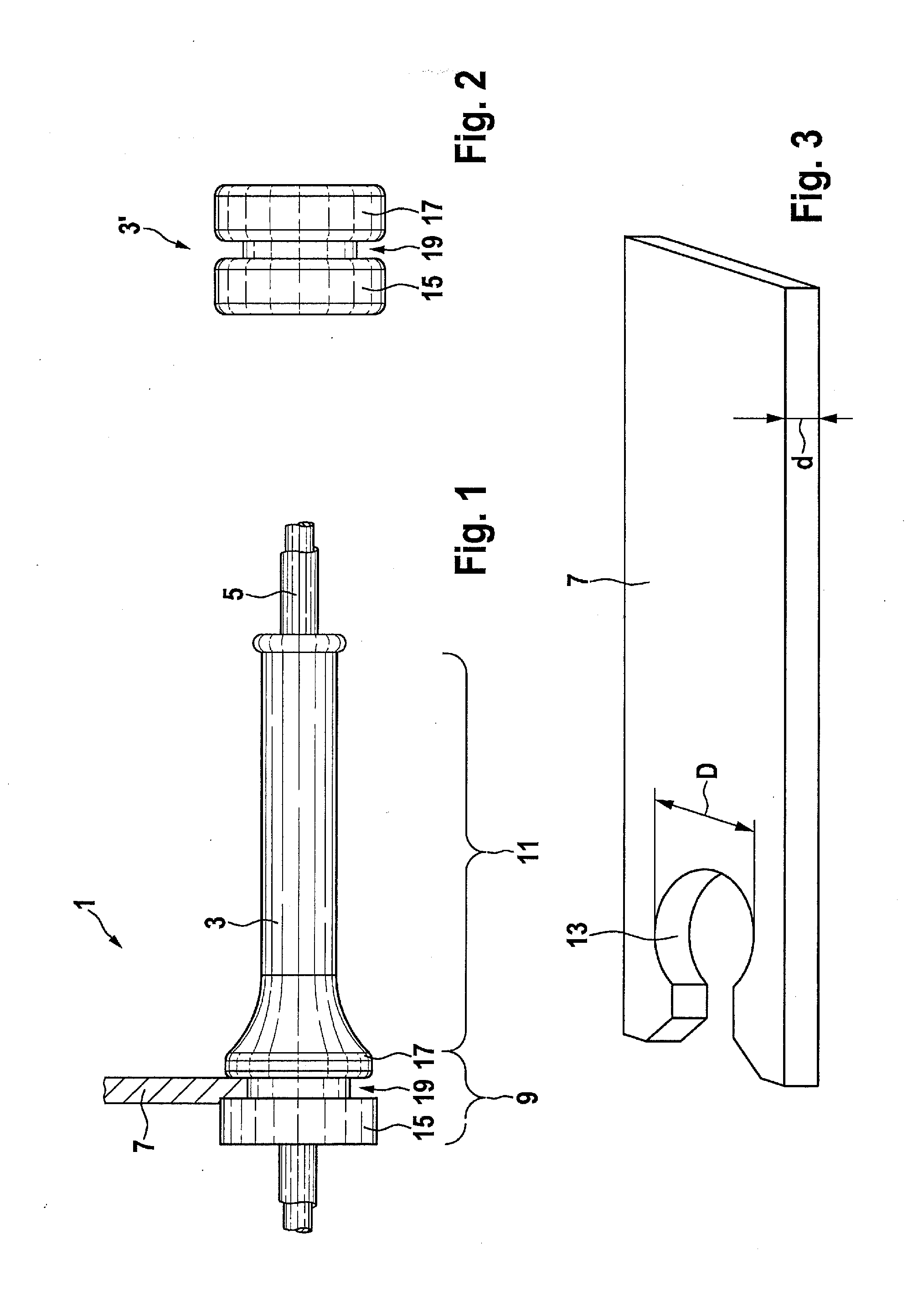
[0037]FIG. 1 shows a side view of a fastening device 1 in which a sleeve 3 completely encloses a line 5 which is designed as an electrical cable and is locked in place on a holder 7. Line 5 may thus be securely fastened, for example inside a vehicle, with the aid of sleeve 3. Sleeve 3 has a static functional area 9 at which sleeve 3 is locked in place on holder 7. In addition, sleeve 3 has a dynamic functional area 11 which encloses line 5 away from holder 7, and which due to its flexibility may reliably hold line 5 in a sealing manner, even under dynamic stress.

[0038]FIG. 2 shows a sleeve 3′ having only a static functional area and no dynamic functional area.

[0039]FIG. 3 shows a perspective view of a holder 7 to which sleeves 3, 3′ may be locked in place. Holder 7 has a circular recess 13 into which sleeves 3, 3′ may be introduced and locked in place therein.

[0040]In the area of their lock on holder 7, sleeves 3, 3′ have two flange-like ridges 15, 17 which delimit a groove-shaped c...


PUM

PropertyMeasurementUnit
Electrical resistanceaaaaaaaaaa
Areaaaaaaaaaaa
Thermoplasticityaaaaaaaaaa

Abstract

A fastening device, e.g., for an electrical cable in a vehicle, has a sleeve which is lockable in a holder and which encloses the line. The sleeve has at least two sleeve subareas which are at least partially separable from one another in such a way that in a preinstalled state the line is inserted into an inner area of the sleeve, and the sleeve subareas are connectable to one another in such a way that in an installed state the line is completely annularly enclosed by the sleeve subareas. Due to the multipart configuration of the sleeve, it is easily mounted on a line. A resistant material such as a thermoplastic elastomer, which is processable with the aid of injection molding, is used for the sleeve.

Description

BACKGROUND OF THE INVENTION[0001]1. Field of the Invention[0002]The present invention relates to a fastening device for fastening a line to a holder, in particular for fastening an electrical cable in a vehicle. Moreover, the present invention relates to a method for fastening a line with the aid of a fastening device according to the present invention.[0003]2. Description of the Related Art[0004]Fastening devices are known from published German patent application document DE 10 2008 008 562 A1, for example, via which lines, for example in the form of flexible electrical cables, may be fastened or locked in place on a holder. The line is enclosed in a sealing manner by a so-called sleeve, sometimes also referred to as a support sleeve. The sleeve may establish an elastic mechanical connection between the line and the holder. For example, the sleeve may have recesses, in particular in the form of grooves, which may be pushed in to fit into recesses in the holder, and may cooperate wi...

Claims


Application Information

Patent Timeline
IPC IPC(8): H02G3/04
CPCH02G3/0406B60R16/0215H02G3/22H02G3/32Y10T29/4995B60R16/02
Inventor WEYRICH, GERDRAUSCH, HELKOWEISHAEUTEL, FRANKBISCHOF, ROLFCACHAY MATEOS, ERASMORITTER, LARSHEGAZI, ANWARKLEINE, JESSICA
Owner ROBERT BOSCH GMBH
Learn More