Seal Arrangement for a Rotating Ship Propeller Shaft

Inactive Publication Date: 2014-02-20
BLOHM VOSS IND
View PDF9 Cites 11 Cited by
  • Summary
  • Abstract
  • Description
  • Claims
  • Application Information

AI Technical Summary

Benefits of technology

The invention provides a seal arrangement for a ship's propeller shaft that is resistant to wear and tear, has a long operating life, and prevents problems associated with existing seal arrangements. The arrangement includes an oil supply line, an oil return line, and an oil circulation pump to achieve a continuous flow of oil in the seal chamber. The arrangement also includes additional oil-filled chambers for redundancy and different oil pressure levels. An oil cooler can be added to reduce the temperature and thermal loading of the seal arrangement.

Problems solved by technology

For example, in large ships, the oil lines supplying oil to the oil-filled chamber must be quite long, which adds to the complexity, cost and weight of the overall system.
In such known systems, there is also the danger of air passing from the pressurized air-filled chamber into the adjacent oil-filled chamber.
This can cause air bubbles and foaming in the lubricating oil, and it may not be possible to completely remove these air bubbles, foam or gas inclusions from the lubricating oil via a ventilation or de-gassing line.
As a result, the oil may provide an inadequate lubricating effect, which leads to more-rapid wear and premature failure or damage of the seal rings.
Furthermore it has been found that the oil present in the oil-filled chamber ages prematurely and loses its required lubricating properties due to strong thermal and mechanical loads and demands being placed on this oil.
Also, this oil can become contaminated with wear particles caused by wear of the seal rings and the bushing, and also can become water-contaminated due to penetration of water past the seal rings into the oil-filled chamber.
It is not possible to regularly exchange the oil in the oil-filled chamber, so that after a certain time of operation, the oil's lubrication effect of the seal rings is no longer optimal, and due to the breakdown of the oil over time a chemical degradation of the seal rings may also arise.

Method used


Image

  • Seal Arrangement for a Rotating Ship Propeller Shaft
  • Seal Arrangement for a Rotating Ship Propeller Shaft
  • Seal Arrangement for a Rotating Ship Propeller Shaft

Examples


Embodiment Construction

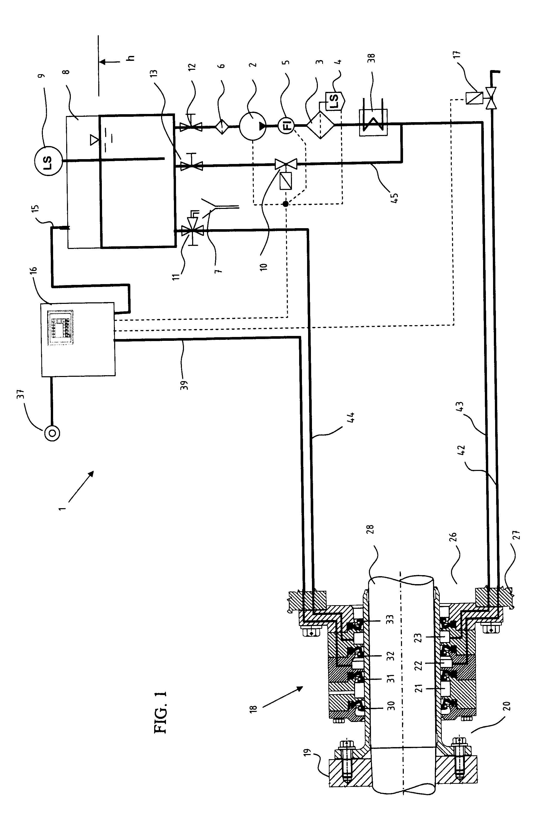
[0020]As shown in FIG. 1, an apparatus according to the invention includes a control arrangement 1 and a seal arrangement 18 as a multiple seal for providing a seal around a propeller shaft 28 that drives a propeller 19 below the waterline outside a hull of a watercraft, after passing outwardly through a stern tube or a stern seal bush housing 27. The “watercraft” can be any ship, boat, submarine etc. that has a buoyant hull operating under, in and / or on the water, and that has a rotating shaft 28 penetrating from a hull interior side to a hull exterior side through the hull. Thus, the seal arrangement 18 is arranged and provides a seal between an exterior seawater area 20 and a lubricating oil area 26 on the interior side, e.g. in the stern tube area. The seal arrangement 18 is controlled and provided with oil and pressurized air by the control arrangement 1, as will be described below.

[0021]In the embodiment according to FIG. 1, the seal arrangement 18 includes three successive se...


PUM

PropertyMeasurementUnit
Lengthaaaaaaaaaa
Lengthaaaaaaaaaa
Heightaaaaaaaaaa

Abstract

A seal arrangement for a ship's propeller shaft includes at least one oil-filled seal chamber bounded by seal rings around the shaft, as well as an oil reservoir tank, an oil supply line connecting the tank to the bottom portion of the seal chamber, an oil circulation pump interposed in the supply line between the tank and the seal chamber, and an oil return line communicating from the upper portion of the seal chamber back to the tank. Thereby, oil is continuously circulated through the seal chamber, and thereby flushes out any contaminant particles, air or water that might enter the seal chamber.

Description

PRIORITY CLAIM[0001]This application is based on and claims the priority under 35 USC 119 of German Patent Application 10 2012 016 447.5, filed on Aug. 18, 2012, the entire disclosure of which is incorporated herein by reference.FIELD OF THE INVENTION[0002]The invention relates to a seal arrangement for sealing around the rotating shaft that drives a ship's propeller, between an exterior water side and an interior side, for example where the rotating shaft passes through a stern tube or bushing that penetrates through the stern of the ship's hull.BACKGROUND INFORMATION[0003]Various types and configurations of seal arrangements, bushings, packing boxes, stuffing boxes and the like are known for providing a seal around the rotating shaft that drives a ship's propeller, where the shaft penetrates through the stern of the ship from the interior to the exterior of the ship's hull. The seal arrangement must effectively prevent water from the exterior environment, i.e. from the exterior of...

Claims


Application Information

Patent Timeline
IPC IPC(8): F16J15/32F16N7/36
CPCF16N7/36F16J15/3232B63H23/321F16J15/406F16J15/16B63H23/36
Inventor WRAGE, MARKOFANGAUF, CARLOS
Owner BLOHM VOSS IND
Why Eureka
Try Eureka