Mtj MRAM with stud patterning
a technology of stud patterning and mtj, which is applied in the direction of magnetic field-controlled resistors, electrical devices, semiconductor devices, etc., can solve the problems of widening (i.e. oversized, increased margin of error), and achieves the effect of higher bias
- Summary
- Abstract
- Description
- Claims
- Application Information
AI Technical Summary
Benefits of technology
Problems solved by technology
Method used
Image
Examples
first embodiment
[0041
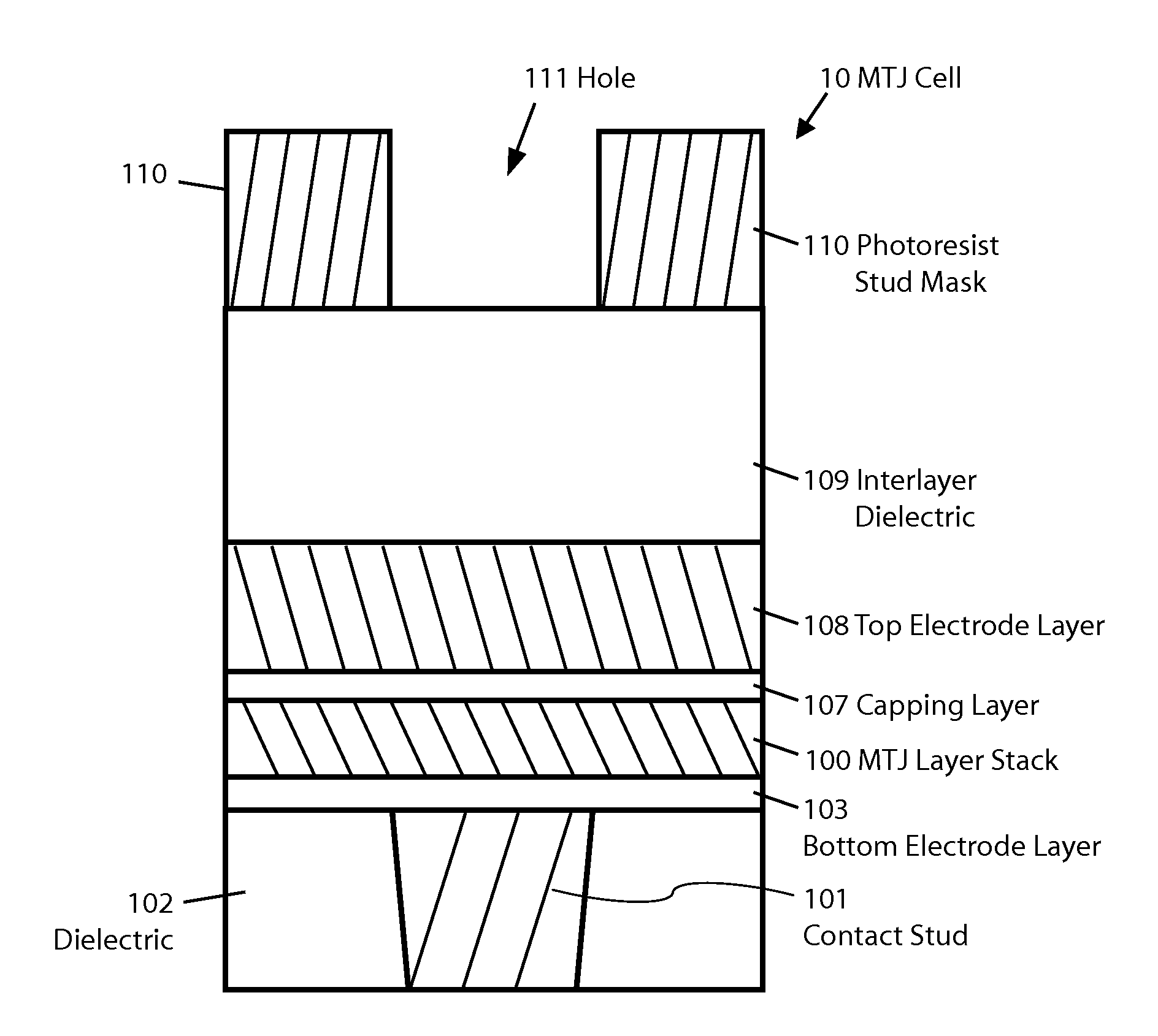
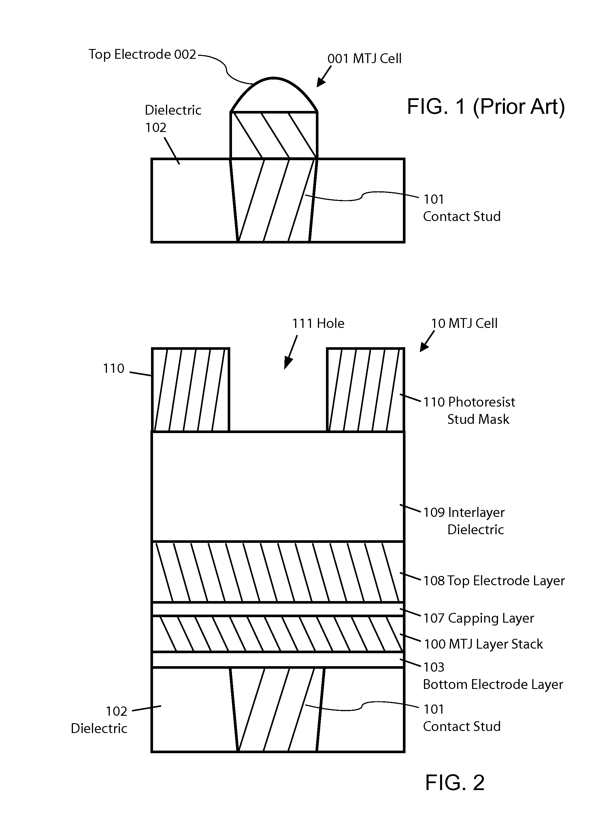
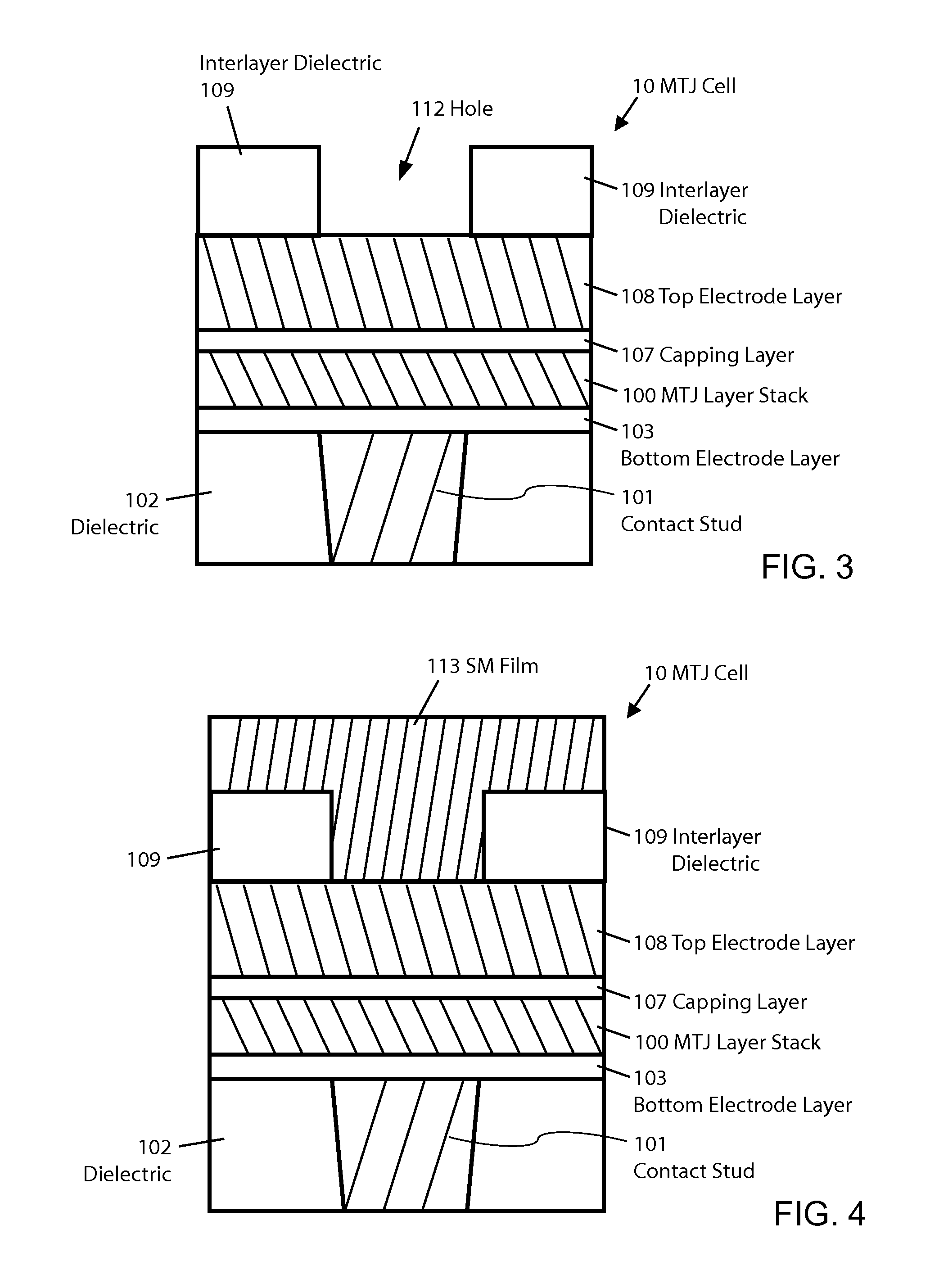
[0042]FIGS. 2 to 6 will be used to describe the stud mask (SM) fabrication process of the first embodiment of the invention. FIG. 2 illustrates a selected stage of the MTJ MRAM fabrication process for MTJ cell 10. FIG. 2 illustrates that the fabrication process has previously patterned landing pad or contact stud 101 which is isolated by interlayer dielectric layer 102 in the conventional way. The plurality of layers for the MRAM cell have been deposited in sequence over the wafer with no patterning. The lowest layer in the cell is the bottom electrode (BE) layer 103, which is followed by the multiple layers in the MTJ layer stack 100 which includes conventional layers (not shown) such as the free and pinned magnetic layers and the barrier layer. Because the magnetic free layer, for example, can be the upper or the lower magnetic according standard MTJ principles, the following description will typically refer only to the upper and lower magnetic layers with the understanding t...
second embodiment
[0053
[0054]FIGS. 16 to 22 illustrate the second embodiment. In this embodiment the stud mask (SM) 213 also works as a top electrode as well in MTJ Cell 12. The SM 213 fabrication process for the second embodiment of the invention is the same as in the first embodiment except that the SM 213 is formed on top of the capping layer 107 and the SM 213 is preferably thicker than SM 113′. The absence of the separate top electrode layer from the second embodiment results in the exposure of the capping layer where the TE was exposed in the first embodiment. Thus, the capping layer will protect MTJ stacks from the ILD etching ambient.
[0055]FIGS. 16 and 17 illustrate the fabrication process of the stud spacer 215. In FIG. 16 the stud mask 213 has been patterned as previously described. The stud spacer layer 215 has been deposited to conform to the underlying topography as shown. The material for the stud spacer layer 215 is same as described in the first embodiment. FIG. 17 shows the result of...
third embodiment
[0061
[0062]The SM fabrication process for the third embodiment of the invention is processed in the same manner as the second embodiment of the invention with the absence of TE. FIG. 23 illustrates subsequent stage after the SM 213 is fabricated for MTJ Cell 13. The remainder process for the third embodiment is different from the first and the second embodiments of the invention. The stud mask spacer sleeve in this embodiment is formed by polymers created during the etching process. Typically net deposition of materials during an etching process is avoided but this embodiment takes advantage of the phenomenon to achieve a desired result. At first the MTJ etching is performed using standard bias parameters, but when MTJ etching reaches the approximate middle of the upper magnetic layer 100U, the substrate bias is lowered below the standard level to allow a net build up of polymer stud spacer 301 on sidewall of the stud mask and the plateau portion of the upper magnetic layer 100U as ...
PUM
 Abstract
Description
Claims
Application Information
 - R&D
- Intellectual Property
- Life Sciences
- Materials
- Tech Scout
- Unparalleled Data Quality
- Higher Quality Content
- 60% Fewer Hallucinations
Browse by: Latest US Patents, China's latest patents, Technical Efficacy Thesaurus, Application Domain, Technology Topic, Popular Technical Reports.
© 2025 PatSnap. All rights reserved.Legal|Privacy policy|Modern Slavery Act Transparency Statement|Sitemap|About US| Contact US: help@patsnap.com


