
Motor control apparatus and motor control method

a technology of motor control and control apparatus, which is applied in the direction of motor/generator/converter stopper, electronic commutator, dynamo-electric converter control, etc., can solve the problems of poor accuracy of stopping position of stepping motor, large noise, and step-out, and achieve simple and quick adjustment of signal output

Active Publication Date: 2014-02-06
CANON KK
View PDF14 Cites 21 Cited by
  • Summary
  • Abstract
  • Description
  • Claims
  • Application Information

AI Technical Summary

Benefits of technology

The motor control apparatus described in this patent can easily and quickly adjust the position detection unit, and can quickly reach the target position even if the motor slips. This is made possible by detecting the presence or absence of step-out during movement and constantly correcting any deviations in the position. The apparatus uses a sinusoidal drive waveform, which allows for control of the phase, and can even cause the motor to move in a smooth and efficient manner.

Problems solved by technology

However, step-out occurs when large loads are imposed on the stepping motor or during high-speed rotation.
However, in the prior art technologies, because a square-wave drive waveform is used and the drive waveform includes harmonic components, a large amount of noise is occurred.
Moreover, with a square-wave drive waveform, the accuracy of the stopping position of the stepping motor is poor.
Moreover, in the conventional technology disclosed in Japanese Patent Laid-Open No. 2005-12955, it is impossible to adjust after the brushless motor has been incorporated into the equipment to be driven.
Setting operations are difficult for adjustment, because the rotor unit required to be exposed to the exterior in order to connect the rotor to an external power source.
Thus, it takes long time for moving to the target position including static stoppage time and the like.

Method used


Image

  • Motor control apparatus and motor control method
  • Motor control apparatus and motor control method
  • Motor control apparatus and motor control method

Examples


Embodiment Construction

[0063]Hereinafter, preferred embodiments of the present invention will be described in detail with reference to the attached drawings. The motor control apparatus and the motor control method are described with illustration of a rotary drive motor, but the present invention can also be applied to a linear drive motor in which the motor shaft conducts linear movement.

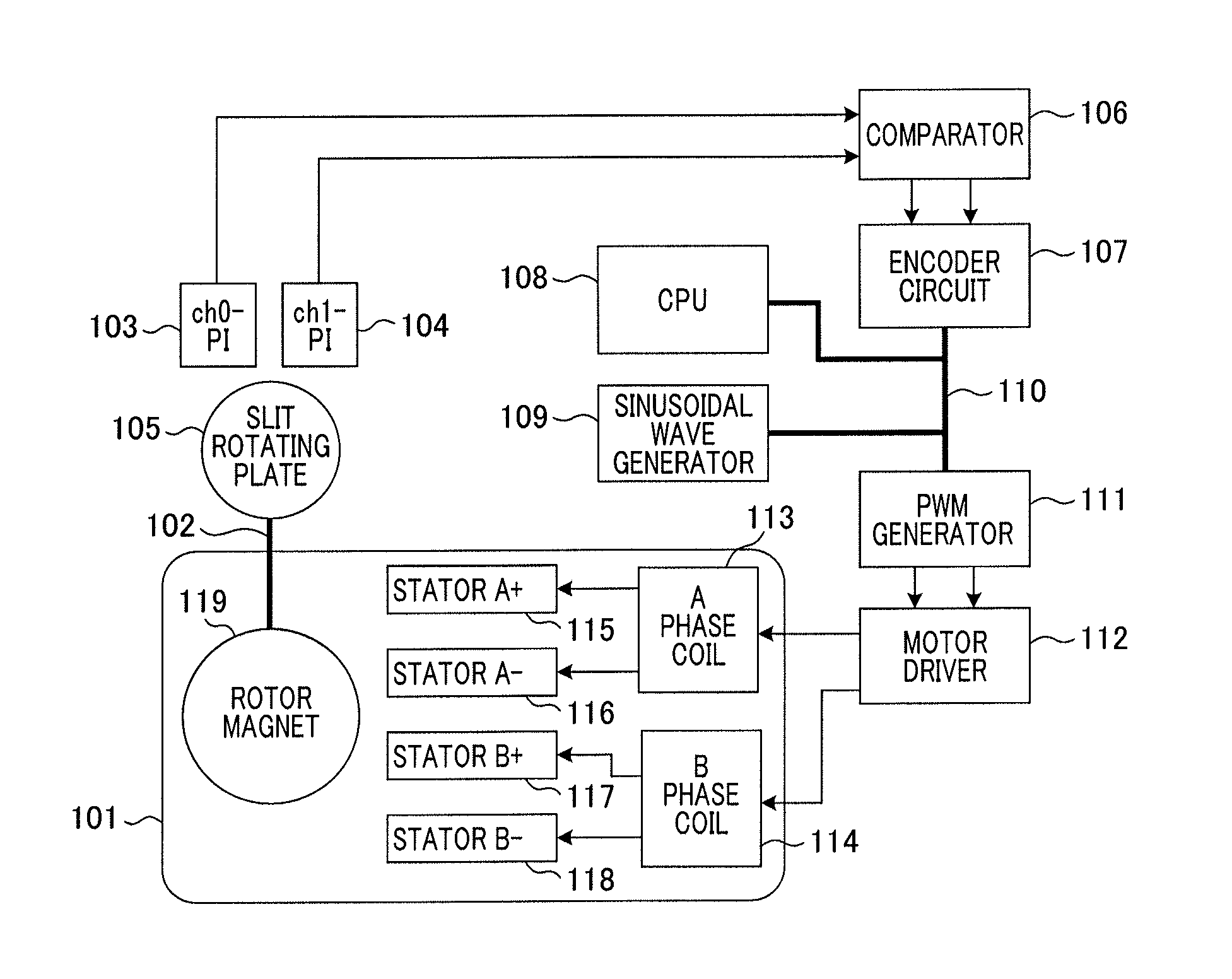
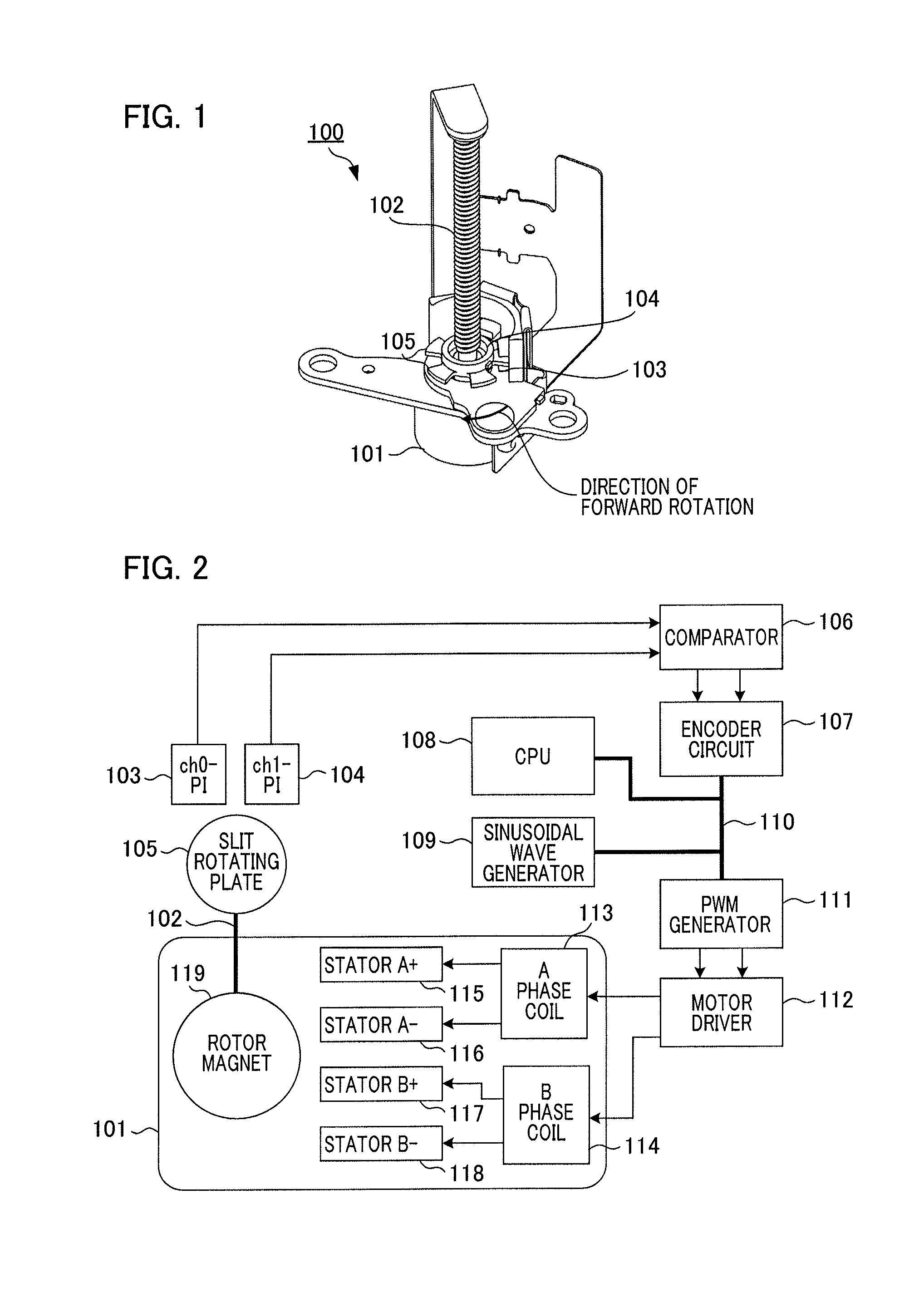
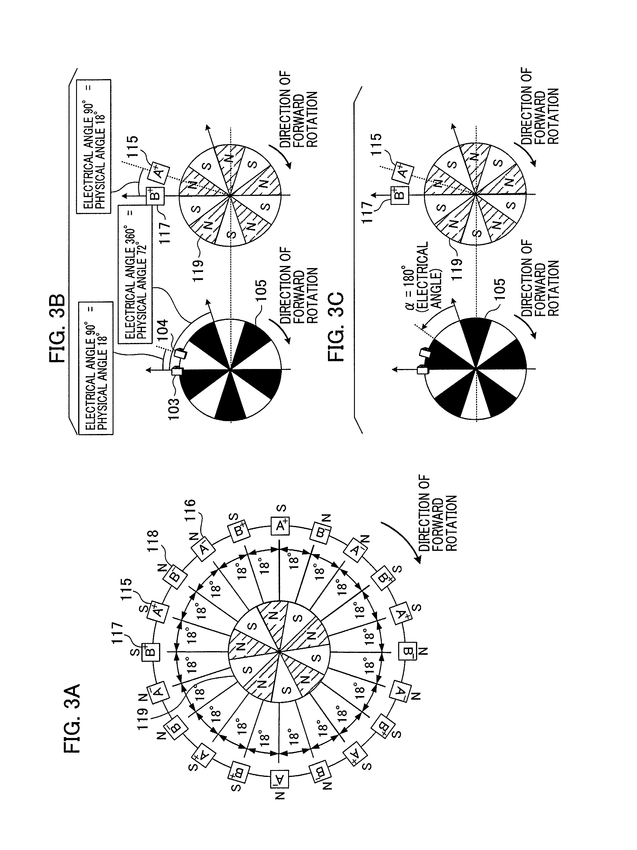
[0064]FIG. 1 is an external view illustrating a motor unit 100 of an embodiment of the present invention. The motor unit 100 comprises a stepping motor 101, and a rotor shaft 102 comprises a slit rotating plate 105. The slit rotating plate 105 is designed so that the ratio of a light region and a dark region is 50:50. As a pair of optical detection units which optically detect the light region and the dark region, a ch0 photointerrupter 103 and a ch1 photointerrupter 104 are attached to the slit rotating plate 105 that is an unit to be detected. The slit rotating plate 105 rotates in conjunction with rotation of the roto...


PUM


Abstract

A motor control apparatus applying a sinusoidal drive waveform to a motor and including a position detection unit outputting a signal according to a motor shaft's position; and a control unit: acquiring a phase value of the motor's drive waveform when a signal is output by the position detection unit, changing a cycle of the drive waveform by measuring time from a previously output signal to a presently output signal, comparing the phases of the drive waveform and the motor shaft, and controlling to change to a cycle at which a phase value of the drive waveform matches a target phase value when a travel time corresponding to a phase value for adjustment has elapsed from a present time when a phase value of the drive waveform presently acquired differs from a target phase value acquired when the motor's drive current and drive voltage are in a designated phase relationship.

Description

BACKGROUND OF THE INVENTION[0001]1. Field of the Invention[0002]The present invention relates to a control apparatus and control method for a motor provided with a position detection unit, and to a technology for enhancing motor drive efficiency.[0003]2. Description of the Related Art[0004]A stepping motor has features such as compact size, high torque, and long life, and enables easy implementation of digital positioning operations by open-loop control. Thus, it is widely used in equipment such as imaging devices, optical disk devices, printers, and projectors. However, step-out occurs when large loads are imposed on the stepping motor or during high-speed rotation. In order to solve this situation, prevention methods that an encoder is attached to the stepping motor and the energization is switched in accordance with a detected position of the rotor, i.e. brushless DC motor operation is performed have previously been performed.[0005]Japanese Patent Laid-Open No. 2002-119089 disclo...

Claims


Application Information

Patent Timeline
Patent Type & Authority Applications(United States)
IPC IPC(8): H02P23/00H02P8/18H02P6/00H02P6/08H02P8/34
CPCH02P23/005H02P6/15H02P8/18
Inventor MIZUO, YOSHIHIRO
Owner CANON KK
Learn More