
Network monitoring device

a network monitoring and monitoring device technology, applied in the field of network monitoring devices, can solve the problems of inability to fully investigate maintenance personnel, inability to monitor the traffic state of the respective communication device, and difficulty in regularly acquiring statistical information from each communication device, so as to achieve the effect of discriminating power discontinuity of a communication device and readily sensed the communication devi

Inactive Publication Date: 2013-12-05
HITACHI LTD
View PDF32 Cites 6 Cited by
  • Summary
  • Abstract
  • Description
  • Claims
  • Application Information

AI Technical Summary

Benefits of technology

The present invention is a network monitoring device that can detect power discontinuity and easily identify devices that are in a zero-traffic state. The device uses information on previous zero-traffic periods to create a new threshold condition for identifying such devices. This helps the system to learn and adapt to different conditions, such as a device being used for a different purpose or being in a maintenance cycle. The device efficiently identifies zero traffic devices and reduces the transmission of unnecessary fault notifications. Overall, the invention improves network monitoring and management.

Problems solved by technology

However, as far as low-reliability and small-sized communication devices are concerned, since the number of communication devices concerned is very large, it is quantitatively difficult to regularly acquire statistical information from each of the communication devices, monitor traffic states of the respective communication devices, and verify communication quality.
However, even the threshold alarm cannot be said to be feasible.
This is because when the threshold alarm is implemented in each of a large number of devices including CPE and a public communication spot device, an event that so many alarms may be given under a certain condition that a maintenance person cannot fully investigate the states of all the devices is predicted.

Method used


Image

  • Network monitoring device
  • Network monitoring device
  • Network monitoring device

Examples


first embodiment

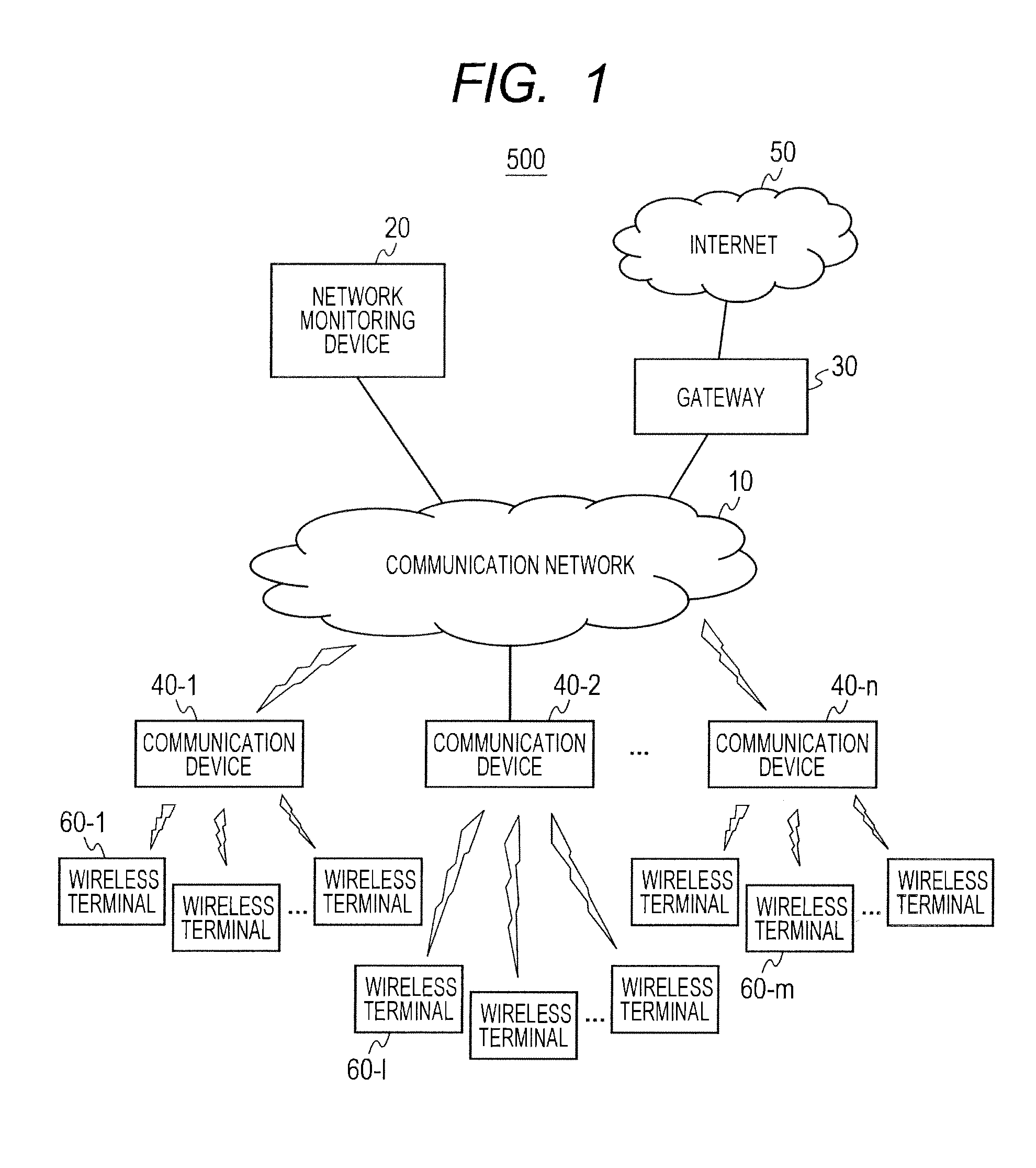
[0050]Referring to FIG. 1, the configuration of a communication system, will be described. In FIG. 1, a communication system 500 includes a communication network 10, a network monitoring device 20, a gateway 30, communication devices 40, the Internet 50, and wireless terminals 60. The network monitoring device 20 is connected onto the communication network 10 by cable. The communication devices 40 are connected onto the communication network 10 by radio or by cable. The network monitoring device 20 remotely monitors the communication devices 40 over the communication network 10. The communication network 10 is connected with the Internet 50 via the gateway 30. The wireless terminals 60 are connected to the communication devices 40 through radio communication. The wireless terminals 60 receive services from the Internet 50 via the communication devices 40 and gateway 30.

[0051]Noted is that the communication devices and wireless terminals in this specification encompass quite wide-ran...

second embodiment

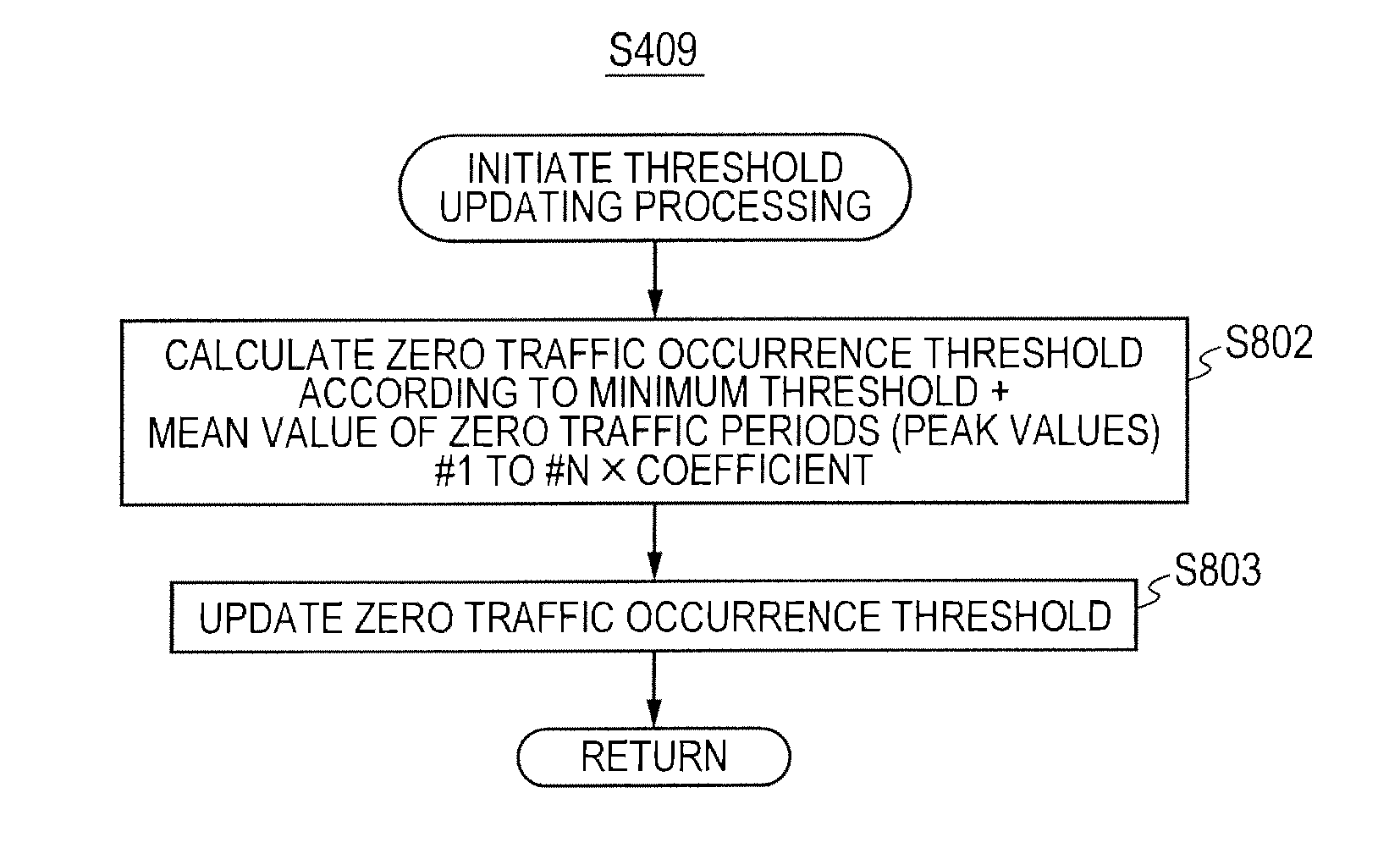
[0097]In the first embodiment, the zero traffic period (peak value) 203 to be employed in calculation of the zero traffic occurrence threshold 201 is regarded as a value of a maximum period which is previously observed in a communication device concerned and traffic is restored (generated), and only the one value is managed.

[0098]In a second embodiment, plural zero traffic periods (peak values) 203 are summated, and a mean value is used to calculate the zero traffic occurrence threshold.

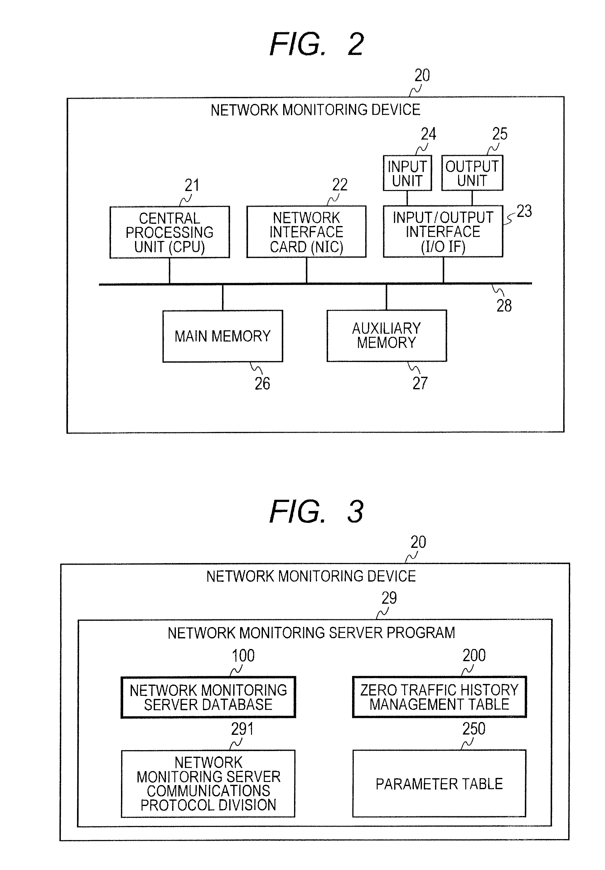
[0099]In the second embodiment, in a system having the system configuration shown in FIG. 1, network monitoring device hardware shown in FIG. 2, network monitoring device shown in FIG. 3, communication devices each shown in FIG. 4, network monitoring server database shown in FIG. 5, parameter table shown in FIG. 6B, and traffic management table shown in FIG. 7, the zero traffic management table has the structure shown In FIG. 14 instead of the structure shown in FIG. 6A. Processing to be performed by...


PUM


Abstract

A zero traffic state that is a non-communication state derived from any fault is discriminated from a no-operation state derived from, power discontinuity, and a communication device that is in the zero traffic state is efficiently sensed in consideration of a zero traffic period that is normally observed in a certain installation place or use environment. A network monitoring device cyclically notifies a maintenance person of a communication device, for which a time difference between a final access time and a finally passed traffic generation time exceeds a threshold calculated by multiplying a previously observed maximum, value of the time difference between the final access time and the finally passed traffic generation time by a coefficient that is a safety factory as a device that is In a zero traffic suspected state.

Description

CLAIM OF PRIORITY[0001]The present application claims priority from Japanese patent application serial no. 2012-127667, filed on Jun. 5, 2012, the content of which is hereby incorporated by reference into this application.BACKGROUND OF THE INVENTION[0002]1. Field of the Invention[0003]The present invention relates to a network monitoring device that monitors communication devices, or more particularly, to a network monitoring device for a system that accommodates many objects of management which have relatively low reliability compared with switching equipment, transmission equipment, or backbone communication equipment and which Include customer premises equipment (CPE), a femtocell base station, a Home Energy Management System (HEMS), a Worldwide Interoperability for Microwave Access (WiMAX) Wireless Fidelity (WiFi) router, and an onboard wireless repeater.DESCRIPTION OF THE RELATED ART[0004]In recent years, communication carriers have come to extensively introduce such facilities...

Claims


Application Information

Patent Timeline
Patent Type & Authority Applications(United States)
IPC IPC(8): H04W24/08
CPCH04W24/08H04L12/2825H04L12/2809H04L29/08099H04L12/2823H04W52/0232H04L43/16H04L67/025Y02D30/70
Inventor KURATA, RYOSUKETAKAHASHI, SHUHEIISHII, HIDEAKI
Owner HITACHI LTD
Learn More