
Metallic compositions useful for brazing, and related processes and devices

a technology of metal compositions and brazing, applied in the field of brazing compositions, can solve the problems of difficult metal-to-ceramic bonding, difficult use of metal-to-ceramic bonding, and the inability of most seals to withstand high temperatures and corrosive environments, and achieve the effect of less complicated processing and less cos

Inactive Publication Date: 2013-11-28
GENERAL ELECTRIC CO
View PDF4 Cites 19 Cited by
  • Summary
  • Abstract
  • Description
  • Claims
  • Application Information

AI Technical Summary

Benefits of technology

This patent describes a braze alloy composition that can be used to join components together through a brazing process. The composition includes nickel, a refractory metal like niobium or tantalum, chromium, and an active metal element like aluminum or zinc. The composition is heated to form an active braze seal between the components, resulting in a strong and durable joint. The technical effects of this invention include improved joining of components and reduced costs compared to traditional methods like welding or cladding.

Problems solved by technology

While mechanisms for sealing these components are currently available, their use can sometimes present some difficulty.
For example, metal-to-ceramic bonding can be challenging, due to thermal stress caused by a mismatch in the coefficient of thermal expansion for the ceramic and metal components.
However, most of the seals may not be able to withstand high temperatures and corrosive environments.
In short, the method is relatively expensive, and complicated, in view of the multiple processing steps, and the difficulty in controlling the processing steps.
However, most of the brazing materials (or braze materials) have limitations that prevent them from fulfilling all of the necessary requirements of high temperature batteries.
Moreover, some of the commercial braze materials can be quite expensive themselves; and using them efficiently in various processes can also be costly.

Method used


Image

  • Metallic compositions useful for brazing, and related processes and devices
  • Metallic compositions useful for brazing, and related processes and devices
  • Metallic compositions useful for brazing, and related processes and devices

Examples


examples

[0065]The example provided herein is merely illustrative, and should not be construed to be any sort of limitation on the scope of the claimed invention. Unless specified otherwise, all ingredients may be commercially available from such common chemical suppliers as Alpha Aesar, Inc. (Ward Hill, Mass.), Sigma Aldrich (St. Louis, Mo.), Spectrum Chemical Mfg. Corp. (Gardena, Calif.), and the like.

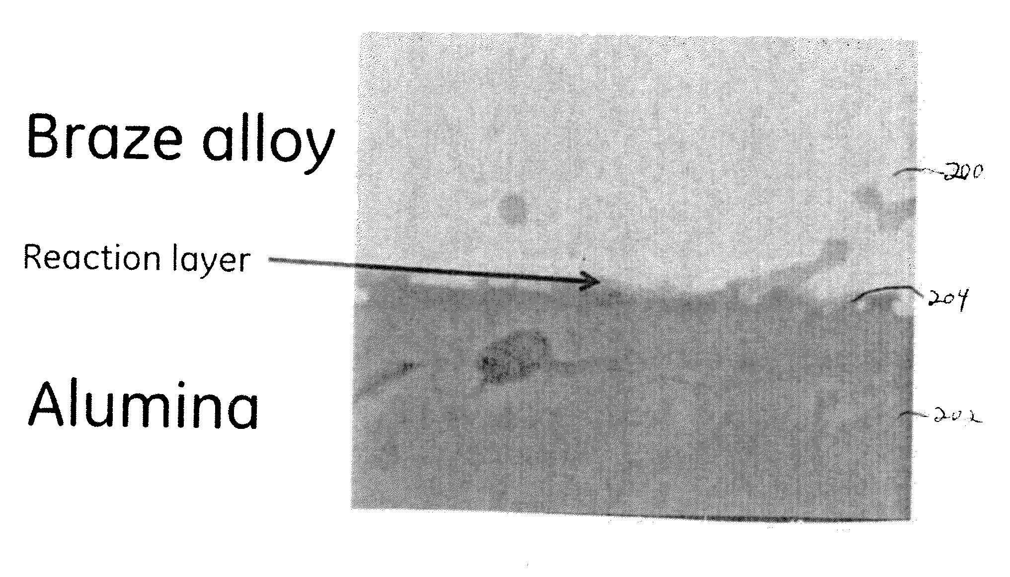
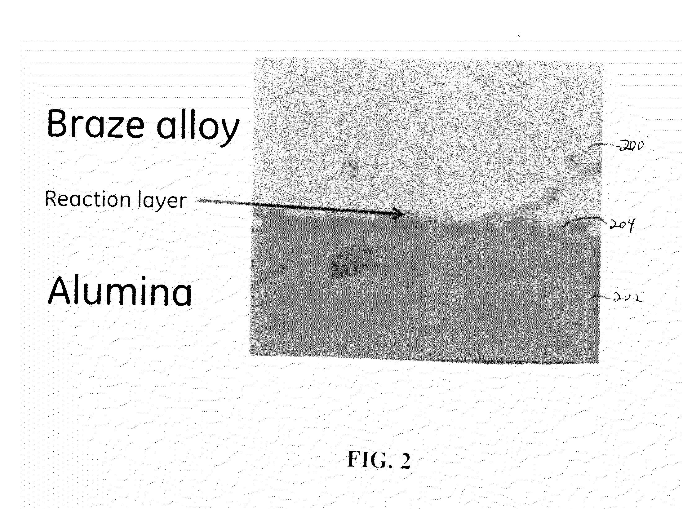
[0066]A braze alloy composition of nickel, chromium, niobium, and titanium was prepared, having the nominal composition Ni-27.2Cr-14.1Nb-4Ti (weight percent). In the preparation of the alloy, the individual elements were weighed according to the desired proportions, and then arc-melted to provide an ingot of the material. To ensure homogeneity of the composition, the ingot was triple-melted. The liquidus temperature of the sample was determined to be 1203° C., using a Differential Scanning Calorimeter (DSC).

[0067]The ingot was formed into approximately a 75 micron-thick sheet, and cooled. The...


PUM

PropertyMeasurementUnit
liquidus temperatureaaaaaaaaaa
weight percentaaaaaaaaaa
liquidus temperatureaaaaaaaaaa

Abstract

A braze alloy composition is disclosed, containing nickel, about 5% to about 40% of at least one refractory metal selected from niobium, tantalum, or molybdenum; about 2% to about 32% chromium; and about 0.5% to about 10% of at least one active metal element. An electrochemical cell that includes two components joined to each other by such a braze composition is also described. A method for joining components such as those within an electrochemical cell is also described. The method includes the step of introducing a braze alloy composition between a first component and a second component to be joined, to form a brazing structure. In many instances, one component is formed of a ceramic, while the other is formed of a metal or metal alloy.

Description

CROSS REFERENCE TO RELATED APPLICATIONS[0001]This application relates to, and claims priority from, the provisionally filed U.S. patent application Ser. No. 61 / 651,817, entitled “Compositions for Brazing, and Related Methods and Devices”, filed on May 25, 2012, which application is hereby incorporated by reference.TECHNICAL FIELD[0002]This invention generally relates to a braze composition. In some specific embodiments, the invention relates to a braze composition that provides corrosion-resistant sealing and other benefits to components used at high temperatures, e.g., thermal rechargeable batteries.BACKGROUND OF THE INVENTION[0003]A variety of electrochemical devices require processes and compositions for providing seals on or within the devices. The seals may be used to encapsulate the entire device, or they may separate various chambers within the device. As an example, many types of seal materials have been considered for use in high-temperature rechargeable batteries / cells for...

Claims


Application Information

Patent Timeline
Patent Type & Authority Applications(United States)
IPC IPC(8): B23K35/24H01M10/02C22C30/00B23K1/20C22C19/05H01M50/186H01M50/191
CPCB23K35/001B23K35/004B23K35/0233B23K35/0238B23K35/3033B23K35/304H01M6/00H01M50/191H01M50/186H01M10/38B23K35/327H01M10/39H01M10/3963B23K35/0244B23K35/025C04B37/006C04B37/026C04B2237/123C04B2237/124C04B2237/127C04B2237/343C04B2237/405C04B2237/70B23K2101/18B23K2101/36B23K2101/38B23K2103/16B23K2103/18B23K2103/26B23K2103/52C22C19/05C22C9/06Y02E60/10H01M50/138Y02P70/50H01M4/02B23K35/30H01M10/02
Inventor KUMAR, SUNDEEPADHARAPURAPU, RAGHAVENDRA RAORAHMANE, MOHAMED
Owner GENERAL ELECTRIC CO
Learn More