
Semi-open-path gas analysis systems and methods

a gas analysis and semi-open-path technology, applied in the field of gas analysis, can solve the problems of rapid information loss and smearing in the tube, and achieve the effects of rapid gas sampling, low power consumption, and rapid measuremen

Active Publication Date: 2013-09-26
LI COR
View PDF11 Cites 11 Cited by
  • Summary
  • Abstract
  • Description
  • Claims
  • Application Information

AI Technical Summary

Benefits of technology

The patent text describes a system and method for measuring the concentrations of sticky and reactive gases in large cells with high flow rates and minimal flow restrictions. The system can also simultaneously measure the pressure and temperature of the sampled gas, resulting in faster and more accurate gas measurements. In addition, the system uses a small-to-large volume sampling cell, which allows for the rapid measurement of many low-concentration trace gases. The intake tubes are wide and short, which minimizes power consumption and enables the sampling of sticky and reactive gases. The simultaneous measurement of gases and air pressure and temperature can also correct for density fluctuations in the sampled gas. Overall, this system provides faster, more accurate, and efficient gas concentration measurements in various settings.

Problems solved by technology

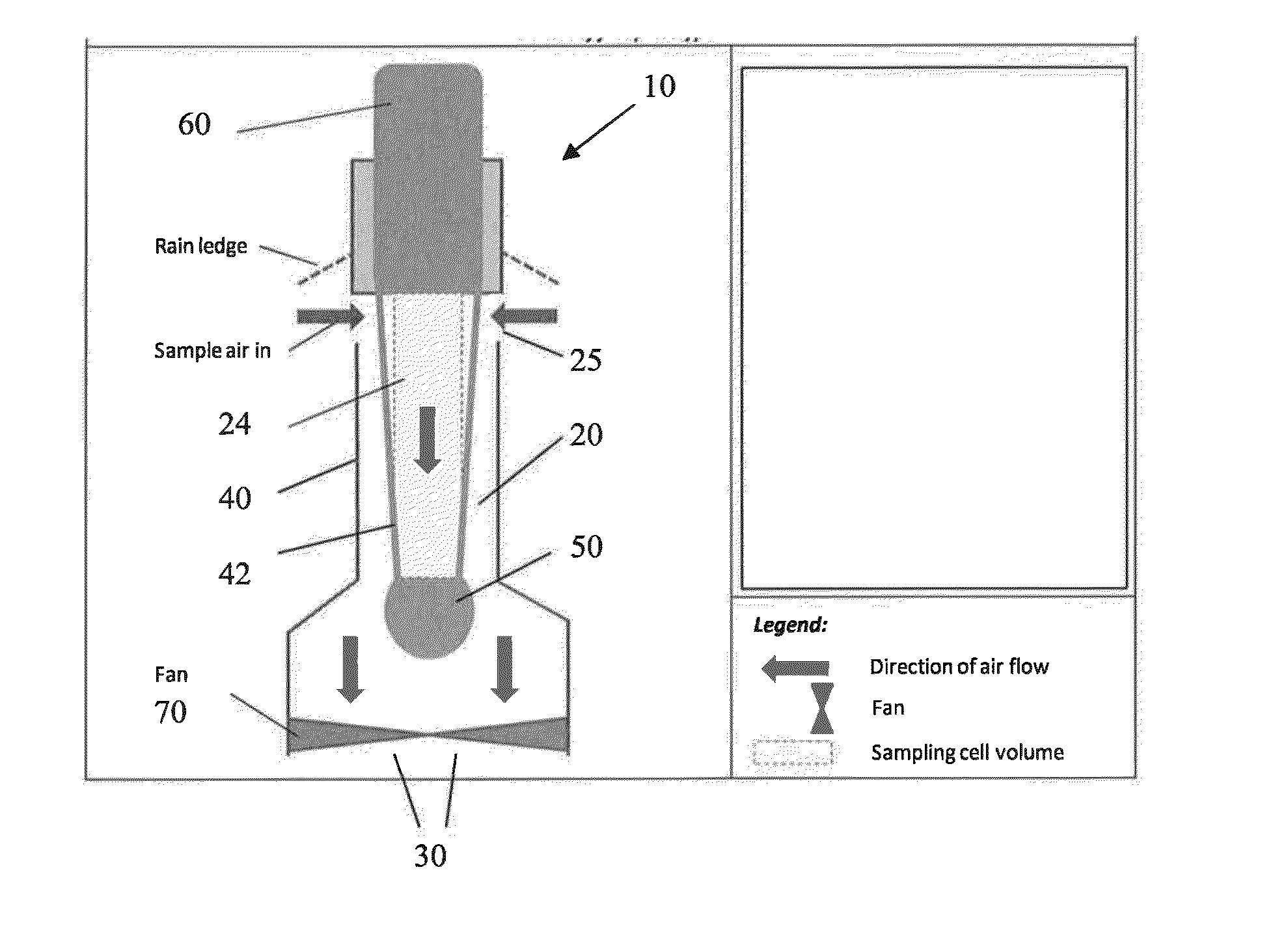
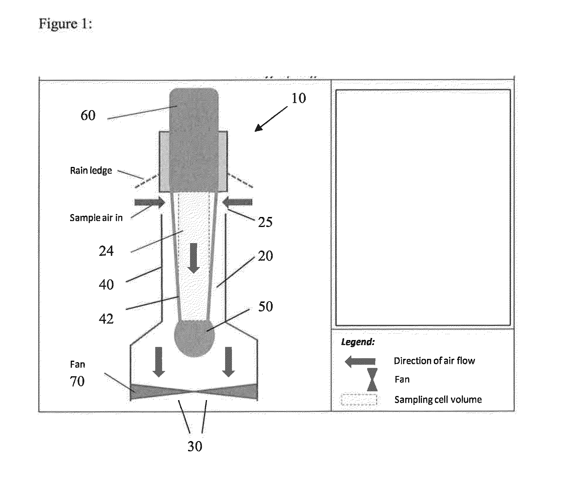
Various embodiments also allow for sampling of sticky gases (such as ammonia, etc.) and highly reactive gases (volatile organic compounds etc.), which currently are not sampled rapidly at all, or sampled inadequately through narrow intake tubes with large area-to-volume ratios leading to smearing of rapid information in the tube, and to loss of information due to physical and chemical reactions between tube walls and the gas.

Method used


Image

  • Semi-open-path gas analysis systems and methods
  • Semi-open-path gas analysis systems and methods
  • Semi-open-path gas analysis systems and methods

Examples


examples

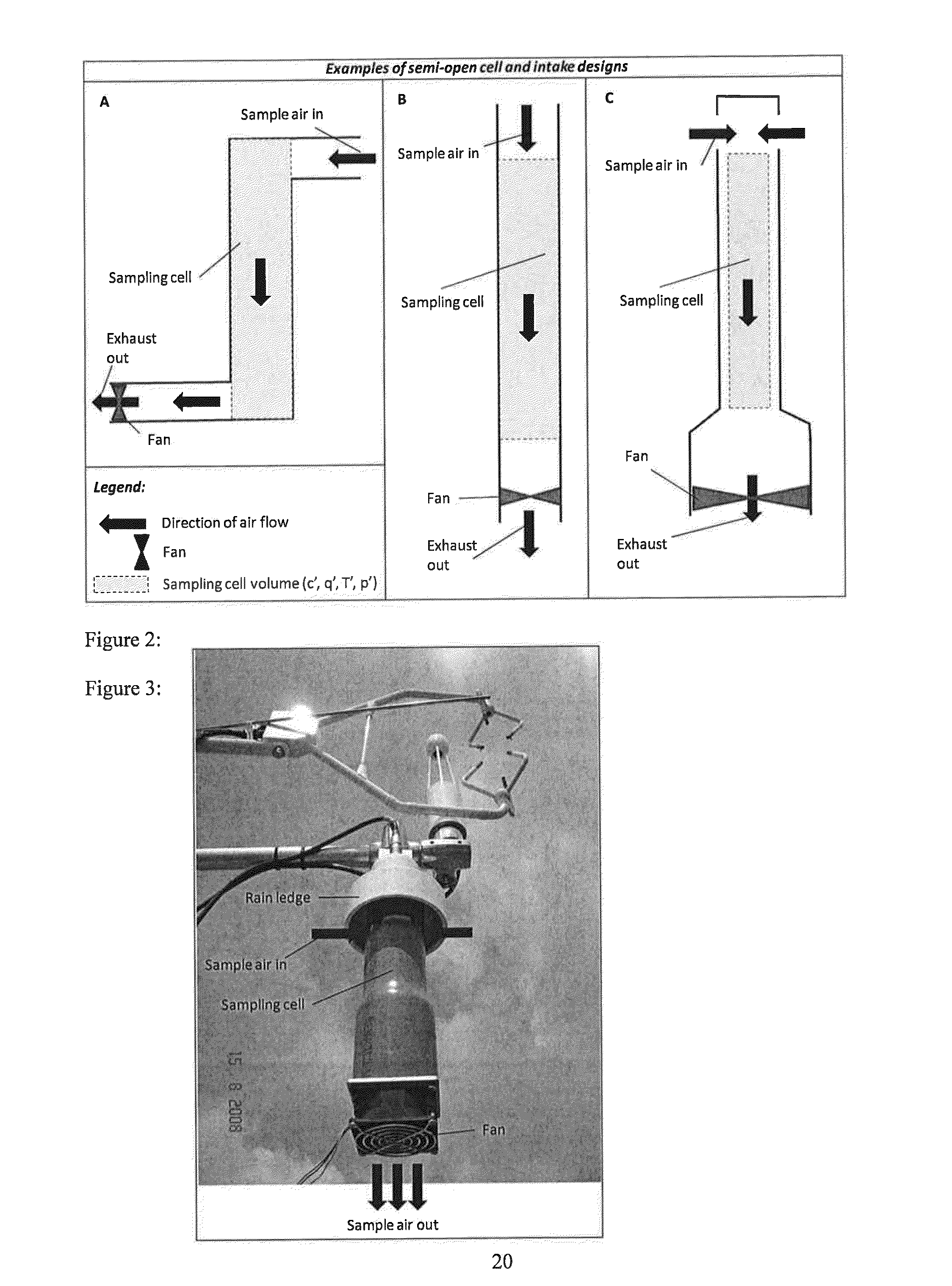
[0037]FIG. 3 illustrates a photograph of a prototype gas analyzer according to one embodiment; the gas analyzer (bottom) is installed and working next to a LI-7500 instrument (top background; from Li-Cor Biosciences) and a sonic anemometer (top foreground).

[0038]FIG. 4(A) illustrates an example of instantaneous time series of CO2 concentrations measured with the LI-7500 instrument and measured with a semi-open-path analyzer embodiment. FIG. 4(B) shows results of the comparison of raw volume-averaging-corrected CO2 fluxes measured with the LI-7500 instrument and measured with the semi-open-path analyzer embodiment. A flow rate of 2400 lpm was provided by a low-power 12V fan. Both instantaneous time series and fluxes from the semi-open-path design were within a few percent from those measured by the LI-7500 reference, proving the practicality and good performance of the embodiment used.

[0039]It should be appreciated that the gas analysis processes described herein may be implemented i...


PUM


Abstract

A gas analyzer includes a detector section including a detector, a source section including a light source, and a support structure coupling the detector section with the source section and forming a flow channel defining an optical path measuring region. The gas analyzer also includes an air flow device configured to pull air through the flow channel from an intake region in the support structure to an exhaust region. Sampling is done by pulling air into the sampling cell via an intake opening or tube of wide diameter and short to medium at very fast flow rates (e.g., 10-3000 lpm or more) enabling rapid gas sampling. Fast flow rates enable the use of large volume cell for rapid gas sampling, which in turn, enables rapid measurements of many low-concentration trace gases and sticky / reactive gases (e.g., methane, ammonia, isotopes of CO2, H2O, nitrous oxide, etc.).

Description

CROSS-REFERENCES TO RELATED APPLICATIONS[0001]NOT APPLICABLESTATEMENT AS TO RIGHTS TO INVENTIONS MADE UNDER FEDERALLY SPONSORED RESEARCH OR DEVELOPMENT[0002]NOT APPLICABLEBACKGROUND[0003]The present invention relates generally to gas analysis, and more particularly to systems and methods for measuring concentrations of gases, including low-concentration or trace gases in the atmosphere.[0004]The increasing concentrations of carbon dioxide and other trace gases in the atmosphere and the resulting greenhouse effect and climate change have become important topics for scientific research. In order to understand the global carbon balance, it is necessary to determine the rate at which carbon dioxide, other trace gases and energy exchanges occur between the atmosphere and terrestrial and oceanic ecosystems. A measurement technique called “eddy covariance” has been widely used to determine these rates. The air within a few hundred meters above the earth surface is mostly turbulent, so that...

Claims


Application Information

Patent Timeline
IPC IPC(8): G01N21/59
CPCG01N21/3504G01N2001/245G01N1/2273G01N21/05
Inventor BURBA, GEORGE G.
Owner LI COR
Learn More