
Systems and methods for attenuation compensation in nuclear medicine imaging based on emission data

a nuclear medicine and emission data technology, applied in the field of nuclear medicine imaging systems, can solve the problems of adding radiation dose to the patient, affecting the quality of reconstructed images in spect systems, and affecting the quality of reconstructed images

Active Publication Date: 2013-09-26
GENERAL ELECTRIC CO
View PDF3 Cites 23 Cited by
  • Summary
  • Abstract
  • Description
  • Claims
  • Application Information

AI Technical Summary

Benefits of technology

The patent describes a method for reconstructing images of a person's body using a radiopharmaceutical that emits radioactive particles. The method involves acquiring emission data at multiple energy windows, including a peak energy window and a scatter energy window. The data is then preliminarily reconstructed to create preliminary images of the energy windows. The person's body outline is determined from the preliminary images, and the left lung is segmented based on the determined body outline. An attenuation map is then created based on the body outline and the segmented left lung. The preliminary images are then jointly estimated using the attenuation map and the peak energy window to create a final image of the person's body. This method allows for more accurate image reconstruction and improved image quality.

Problems solved by technology

While such conventional systems may provide quality images with good diagnostic value, photon attenuation is a major physical factor affecting the quality of reconstructed images in SPECT systems.
These methods currently mostly rely on direction transmission measurements that may include a radioactive source that is often ineffective or measurements from an x-ray computed-tomography (CT) system that are costly, as well as can add radiation dose to the patient, additional imaging time, geometrical mis-registration and resolution differences.
Moreover, because of the high variability of patient sizes and shapes, a “patient standard” can yield a poor reconstruction result.

Method used


Image

  • Systems and methods for attenuation compensation in nuclear medicine imaging based on emission data
  • Systems and methods for attenuation compensation in nuclear medicine imaging based on emission data
  • Systems and methods for attenuation compensation in nuclear medicine imaging based on emission data

Examples


Embodiment Construction

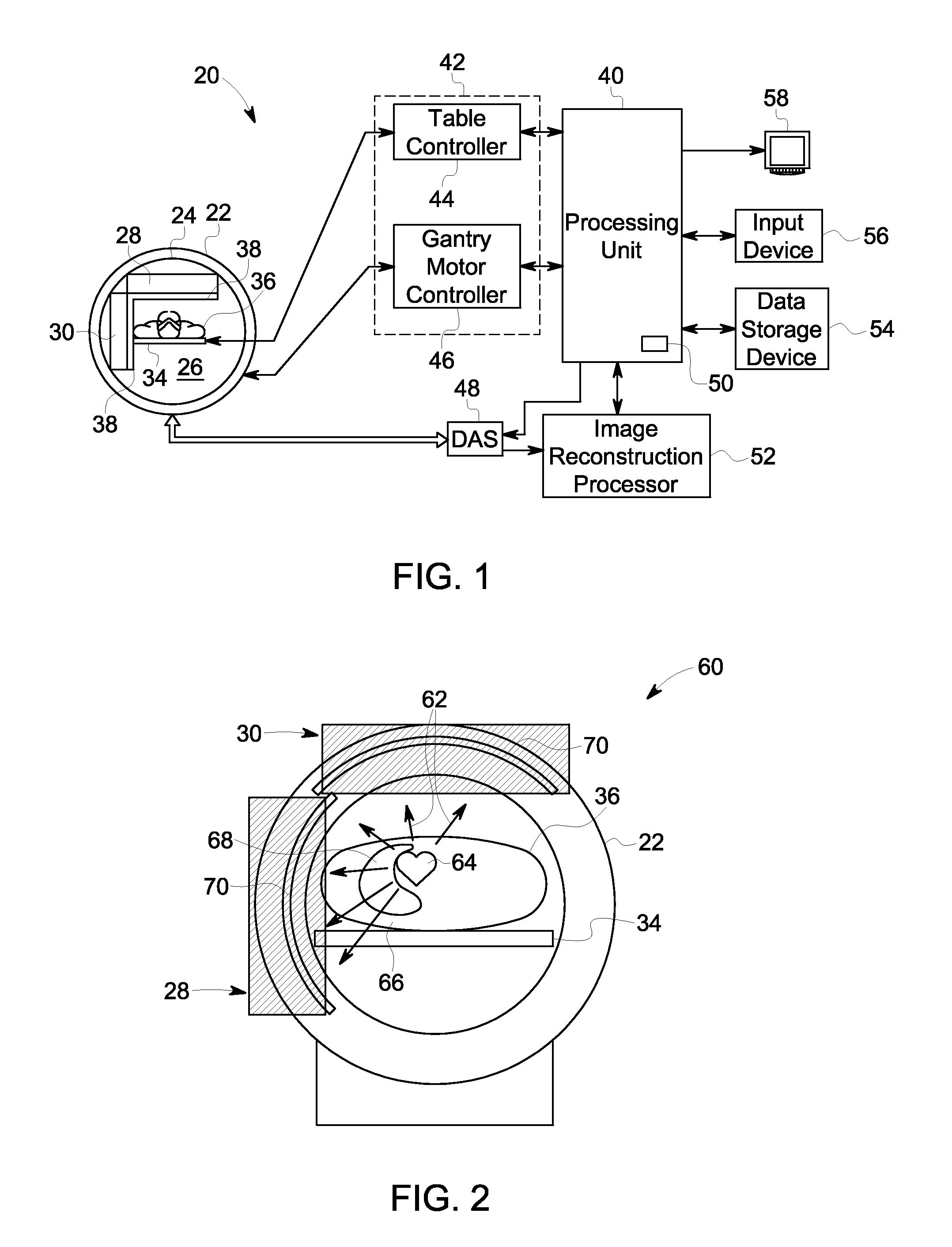
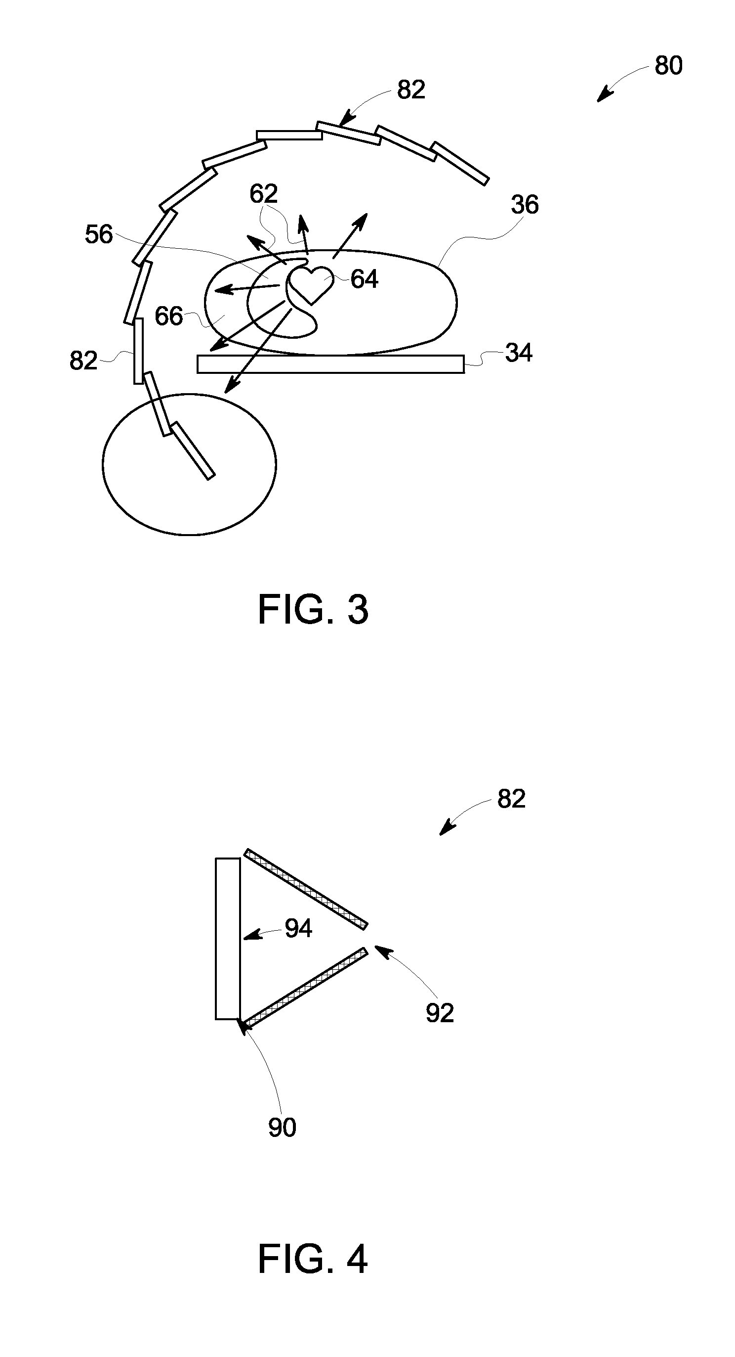
[0021]The foregoing summary, as well as the following detailed description of various embodiments, will be better understood when read in conjunction with the appended drawings. To the extent that the figures illustrate diagrams of the functional blocks of the various embodiments, the functional blocks are not necessarily indicative of the division between hardware circuitry. Thus, for example, one or more of the functional blocks (e.g., processors or memories) may be implemented in a single piece of hardware (e.g., a general purpose signal processor or a block of random access memory, hard disk, or the like) or multiple pieces of hardware. Similarly, the programs may be stand-alone programs, may be incorporated as subroutines in an operating system, may be functions in an installed software package, and the like. It should be understood that the various embodiments are not limited to the arrangements and instrumentality shown in the drawings.

[0022]Described herein are systems and m...


PUM


Abstract

Systems and methods for attenuation compensation in nuclear medicine imaging based on emission data are provided. One method includes acquiring emission data at a plurality of energy windows for a person having administered thereto a radiopharmaceutical comprising at least one radioactive isotope. The method also includes performing a preliminary reconstruction of the acquired emission data to create one or more preliminary images of a peak energy window and a scatter energy window and determining a body outline of the person from at least one of the reconstructed preliminary image of the peak energy window or of the scatter energy window. The method further includes identifying a heart contour and segmenting at least the left lung. The method additionally includes defining an attenuation map based on the body outline and segmented left lung and reconstructing an image of a region of interest of the person using an iterative joint estimation reconstruction.

Description

BACKGROUND OF THE INVENTION[0001]The subject matter disclosed herein relates generally to nuclear medicine imaging systems, and more particularly to single photon emission computed tomography (SPECT) imaging systems and compensating for emission attenuation in SPECT systems, especially in cardiac imaging, using emission data.[0002]Different types of imaging techniques are known and used for medical diagnostic imaging. For example, diagnostic nuclear imaging, such as SPECT imaging, is used to study radionuclide distribution in a subject, such as a patient. Typically, one or more radiopharmaceuticals or radioisotopes are injected into the patient. Gamma camera detector heads, typically including a collimator, are placed adjacent to a surface of the patient to capture and record emitted radiation to thereby acquire image data. Different configurations are known wherein the gamma cameras may remain in a fixed location / orientation (e.g., focused detector modules) relative to an object of...

Claims


Application Information

Patent Timeline
Patent Type & Authority Applications(United States)
IPC IPC(8): G01T1/164
CPCA61B6/037A61B6/5205A61B6/5258A61B2576/023A61B6/52A61B6/483A61B6/503G06T11/005G16H30/40A61B6/03
Inventor VOLOKH, LANAHEFETZ, YARONGANIN, ALEXANDERMANJESHWAR, RAVINDRA
Owner GENERAL ELECTRIC CO
Learn More