
Sensorless ac motor controller

a sensorless ac motor and controller technology, applied in the direction of synchronous motor starters, commutation monitoring, modelling/simulation of control, etc., can solve the problems of reducing the reliability of the motor, low cost, poor performance due to mechanical vibration

Active Publication Date: 2013-08-29
HUNTER GREGORY PETER
View PDF3 Cites 101 Cited by
  • Summary
  • Abstract
  • Description
  • Claims
  • Application Information

AI Technical Summary

Benefits of technology

The patent describes a stability control component that uses a filter to improve speed feedback stability. Another component prevents over-modulation of the multiphase drive voltage outputs. The output controller regulates output impedance in a specific way to damp rotor oscillations. These technical effects result in improved performance and stability of the motor.

Problems solved by technology

Also used in much lower quantities are the wound rotor synchronous motor (for high power), the synchronous reluctance motor (for very rugged environments) and the switched reluctance motor (low cost but poor performance due to mechanical vibrations).
The problem with this sensor is that it costs money (for small motors it can cost more than the motor itself), it puts restrictions on the motor's operating environment (the sensor is much less rugged than the motor), it reduces the reliability of the motor, and the extra leads to connect the sensor to the controller must be accommodated.
However even though the research effort has been intense for a long time, only limited commercial success has been achieved.
This method does not work at higher speeds due to instabilities encountered when the speed matches a mechanical resonance and due to distortion of the current waveforms from the rising back EMF voltage.
For applications requiring high torque at zero speed, fast speed reversal, or the application of smooth sinusoidal currents for smooth torque output, the above methods do not work.
There are two obstacles to using this method, particularly at very low speeds.
First, it is very difficult to sense and filter the motor terminal voltages and currents to extract the rotor speed and position with minimal delay time at the low end of the speed range and second, the motor resistance changes with motor temperature making it very difficult to obtain accurate values for it.
Unfortunately, this requires a specially designed motor in which the winding inductance varies in a predictable way with rotor position.
For many applications, including direct drive washing machine motors, the use of motors of this type is not possible, due to their higher cost and design restrictions.

Method used


Image

  • Sensorless ac motor controller
  • Sensorless ac motor controller
  • Sensorless ac motor controller

Examples


Embodiment Construction

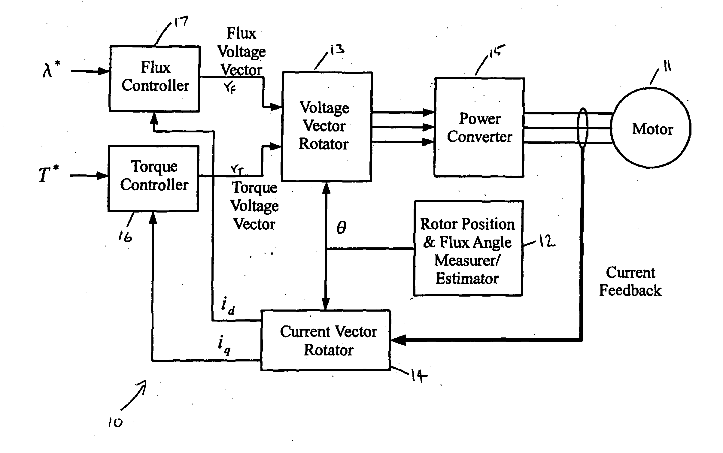
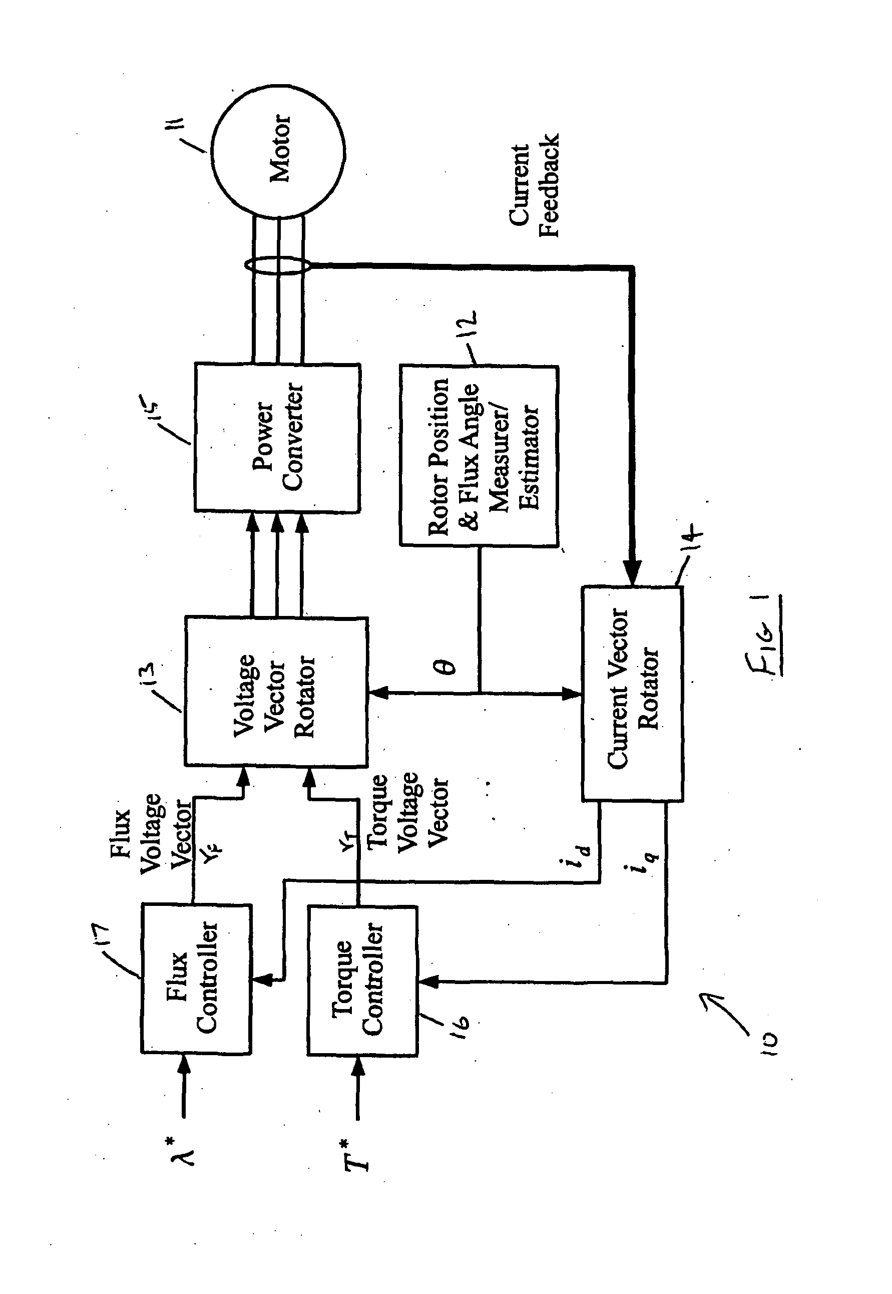
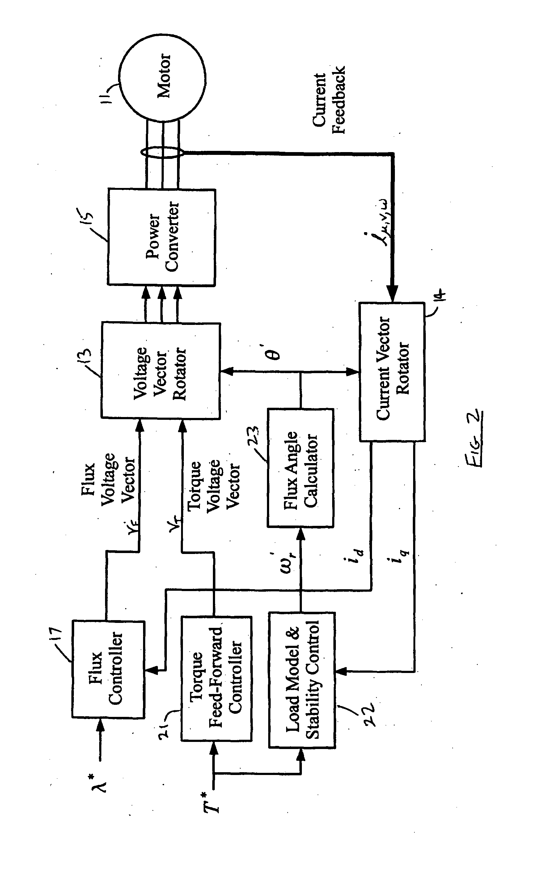
[0137]Feed Forward Torque Control (FFTC) is a new technique for sensorless control of the PMSM which approaches the sensorless control problem in a different way to previous research.

[0138]All previous methods, except the stepper motor, are based around estimating the rotor position motor terminal measurements instead of measuring it directly. FFTC uses the reverse of this process. FFTC starts with the required motor torque then calculates the wanted motor position from a model of the load and the required motor voltages from an inverted model of the motor (which converts motor currents to voltages instead of voltages to currents). Errors between the rotor position applied to the motor and the actual rotor position are corrected at high speed by using the error in the motor currents to correct the load model and at low speed by increasing the motor current in the correct phase sequence to lock in the rotor position, similar to a stepping motor. Standard speed and position feedback l...


PUM


Abstract

A controller for an AC electric motor, includes a Feed Forward Torque Controller and a load model. The Torque controller directly derives a torque related component of applied motor voltages from a signal representing a torque command input T* and at least one motor parameter. The load model derives a motor speed value including a model of motor speed behaviour of the AC electric motor to provide an output signal which represents the motor speed of the AC electric motor. This motor speed output signal is used in determining a frequency of rotation of an applied motor voltage vector. Where an input to the load model is the signal representing the torque command input T*, the load model uses the signal representing the torque command T*, at least over a part of an operating speed range of the AC motor which includes zero speed, to determine the motor speed output signal.

Description

INTRODUCTION[0001]The present invention relates generally to the field of AC motor speed control and in particular an improved speed controller is provided which employs Feed Forward Torque Control (FFTC) for controlling the torque and speed of an electric motor without the use of sensors for measuring the rotor angular position or speed of rotation.BACKGROUND[0002]The two main types of alternating current motors used in the world are the induction motor and the permanent magnet synchronous motor (PMSM). Also used in much lower quantities are the wound rotor synchronous motor (for high power), the synchronous reluctance motor (for very rugged environments) and the switched reluctance motor (low cost but poor performance due to mechanical vibrations).[0003]To speed control the induction motor, all that is needed is to supply alternating currents to the windings and vary their frequency to vary the motor speed. For all the other types of motors, a rotor position sensor is normally als...

Claims


Application Information

Patent Timeline
Patent Type & Authority Applications(United States)
IPC IPC(8): H02P6/00
CPCH02P21/0003H02P6/001H02P21/146H02P21/0042H02P6/34H02P21/26H02P21/18
Inventor HUNTER, GREGORY PETER
Owner HUNTER GREGORY PETER
Learn More