Eureka AIR delivers breakthrough ideas for toughest innovation challenges, trusted by R&D personnel around the world.

Braking control system and braking control method

a technology of braking control system and braking control method, which is applied in the direction of braking system, analogue process for specific applications, instruments, etc., can solve the problems of how to release the braking force and the behavior of the vehicle may become unstable, and achieve the effect of preventing the behavior of the vehicle from becoming unstabl

Inactive Publication Date: 2009-12-31
TOYOTA JIDOSHA KK
View PDF10 Cites 37 Cited by
  • Summary
  • Abstract
  • Description
  • Claims
  • Application Information

AI Technical Summary

Benefits of technology

The present invention provides a braking control system and method for vehicles that cancels automatic braking when a collision with an object is predicted and automatic braking is started, while preventing the vehicle from becoming unstable when a collision is avoided through a steering operation by the driver. This results in a more stable vehicle behavior during times when the driver steers to avoid the object. The braking device can increase the duration of automatic braking and decrease the gradient with which to reduce the braking force to restrict changes in pitch of the vehicle. The braking device can also set the magnitude or duration of the automatic braking based on the behavior of the vehicle, making it more appropriate for the situation. Overall, this invention allows for safer and more stable driving habits.

Problems solved by technology

The system described in Japanese Patent Application Publication No. 2003-175809 (JP-A-2003-175809), however, does not discuss how to release the braking force after automatic braking is started and when a collision is avoided through a steering operation by the driver.
If the automatic braking is canceled abruptly, the behavior of the vehicle may become unstable.

Method used


Image

  • Braking control system and braking control method
  • Braking control system and braking control method
  • Braking control system and braking control method

Examples


Embodiment Construction

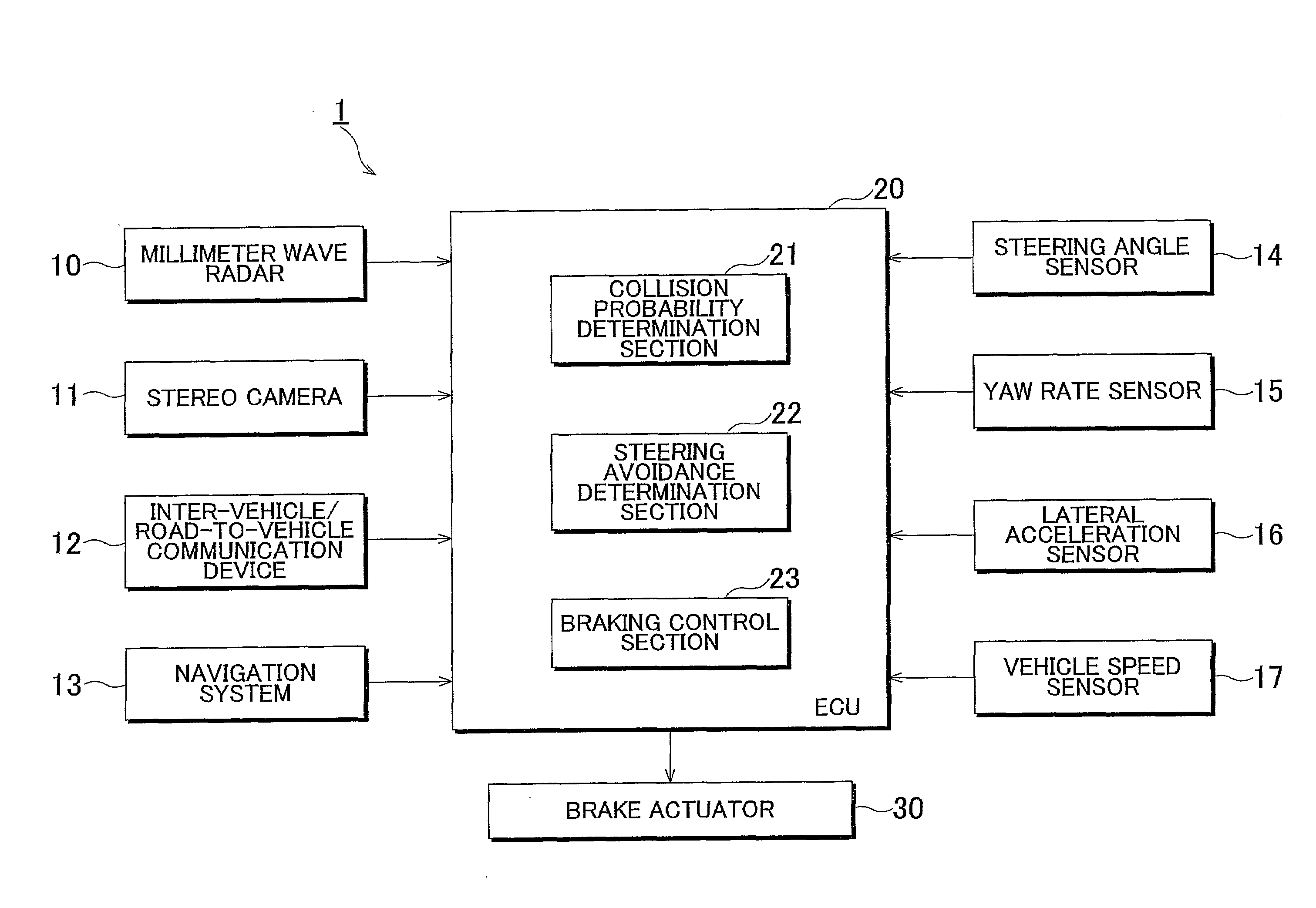
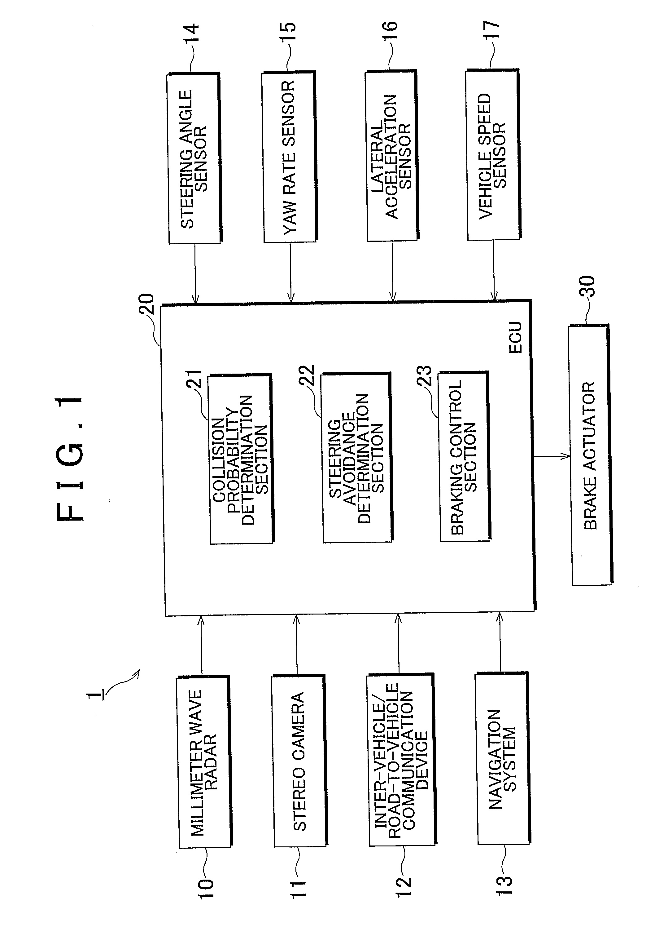
[0024]An example embodiment of the present invention will be described in detail below with reference to the drawings. In the drawings, the same reference numerals denote the same or corresponding component parts. First, the configuration of a braking control system 1 in accordance with the embodiment is described with reference to FIG. 1. FIG. 1 is a block diagram showing the configuration of the braking control system 1.

[0025]In the braking control system 1, a millimeter wave radar 10, a stereo camera 11 and so forth recognize another vehicle or an object in the path of the vehicle. An electronic control unit (hereinafter referred to as “ECU”) 20 determines the likelihood of collision with the object based on the distance, speed, and direction of the vehicle relative to the object. If it is determined that the likelihood of collision is high, the ECU 20 drives a brake actuator 30 to perform automatic braking, independently of operation of a brake pedal, in order to decelerate the ...


PUM


Abstract

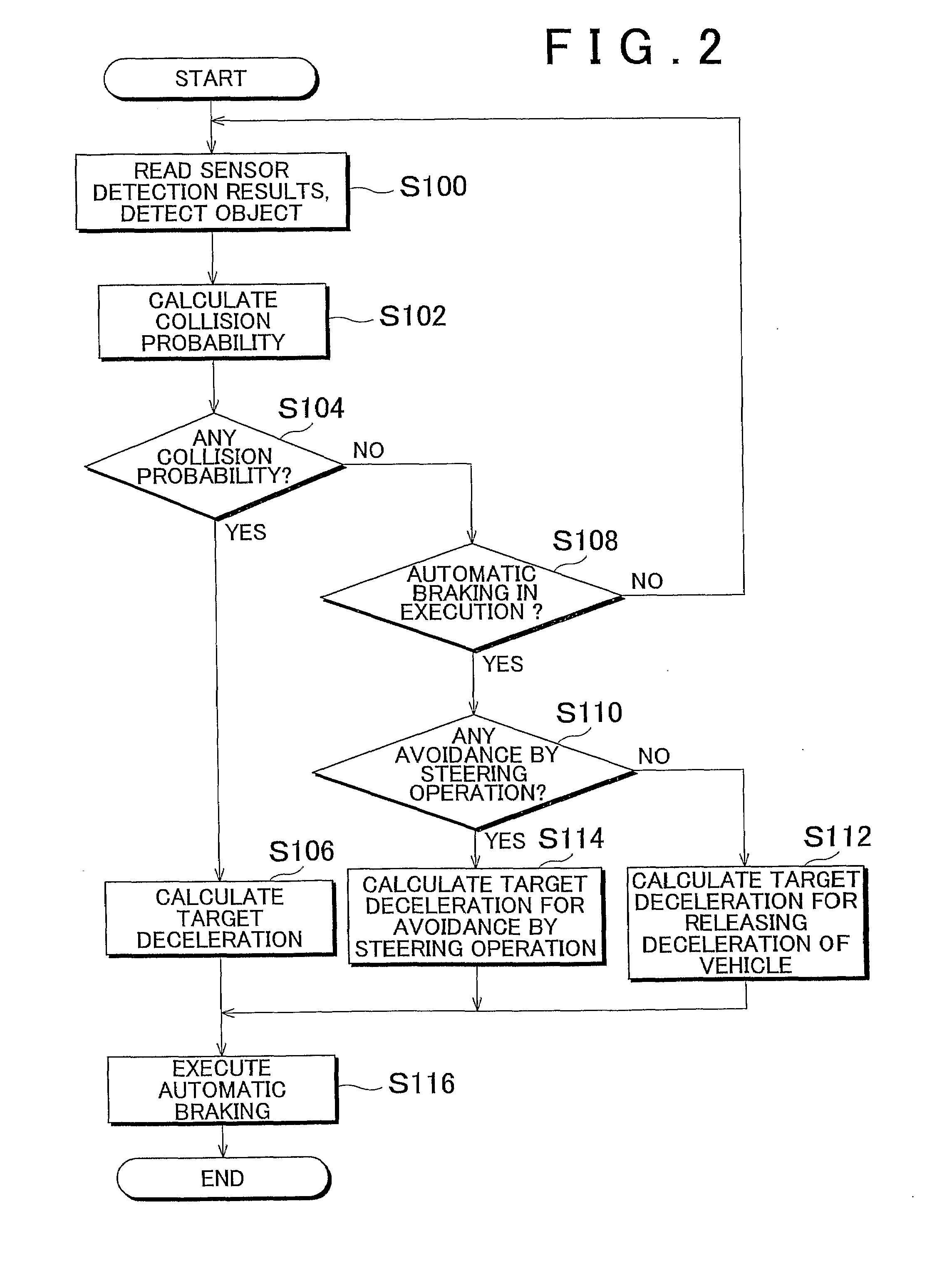
A braking control system (1) includes: an ECU (20) that determines the likelihood of collision with an object based on detection results by a millimeter wave radar (10), a stereo camera (11) and the like; a brake actuator (30) that automatically applies a braking force based on the determination results; a steering angle sensor (14) that detects the steering condition by a driver; and so forth. When it is determined that a collision with an object is likely and automatic braking is started, and it is subsequently determined that a collision with the object is avoided through a steering operation by the driver, the ECU (20) sets a smaller gradient with which the target deceleration (target braking force) in the automatic braking is reduced in comparison to when a collision with the object is avoided not through the steering operation by the driver.

Description

BACKGROUND OF THE INVENTION[0001]1. Field of the Invention[0002]The present invention relates to a braking control system and braking control method for a vehicle.[0003]2. Description of the Related Art[0004]In an existing braking control system for a vehicle, a braking force is automatically generated to avoid colliding with an object, such as a preceding vehicle, when it is determined that a collision with the object is likely. Japanese Patent Application Publication No. 2003-175809 (JP-A-2003-175809) describes a braking control system for a vehicle in which a gradually increasing braking force is generated when it is predicted that avoidance by braking and / or steering will be impossible after a specified time elapses, and a larger braking force is generated when avoidance by braking and / or steering actually becomes impossible.[0005]The system described in Japanese Patent Application Publication No. 2003-175809 (JP-A-2003-175809), however, does not discuss how to release the braki...

Claims


Application Information

Patent Timeline
Patent Type & Authority Applications(United States)
IPC IPC(8): G08G1/16B60T7/12
CPCB60T7/22B60T2201/022B60W2550/20B60W30/18172B60W2420/52B60W30/08B60W2554/00B60W2420/408
Inventor SHIMIZU, MASAYUKI
Owner TOYOTA JIDOSHA KK
Why Eureka
Eureka Blog
Learn More