
TSV Backside Processing Using Copper Damascene Interconnect Technology

a backside processing and copper damascene technology, applied in the direction of semiconductor devices, semiconductor/solid-state device details, electrical apparatus, etc., can solve the problems of imposing limitations on the overall layout, the simple reduction of feature size is rapidly approaching the limit of what can presently be achieved in only two dimensions, and the overall layout is increasingly becoming more complex and more densely packed

Active Publication Date: 2013-05-02
GLOBALFOUNDRIES SINGAPORE PTE LTD
View PDF1 Cites 13 Cited by
  • Summary
  • Abstract
  • Description
  • Claims
  • Application Information

AI Technical Summary

Benefits of technology

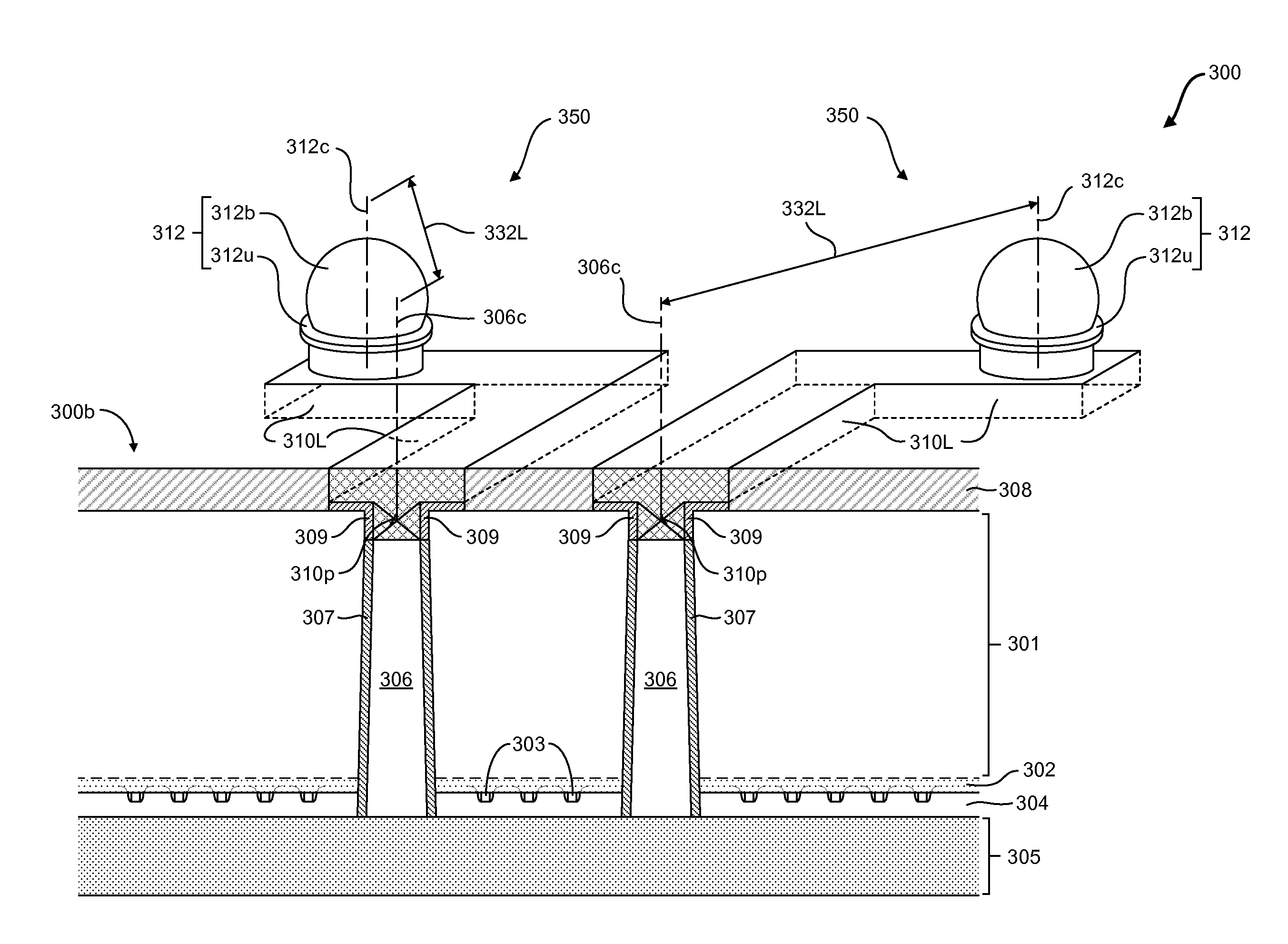
The patent text discusses methods for making connections between semiconductor chips in a stacked or 3D chip configuration. The techniques involve forming conductive elements in the substrate and filling them with conductive material to create interconnect structures that can be used to connect the chips. The patent also describes a method that allows for the creation of a via opening and a conductive contact plug in the back of the substrate, as well as a metal line on top of the via opening. Overall, the patent presents a way to create complex interconnect structures for efficient chip-to-chip communication.

Problems solved by technology

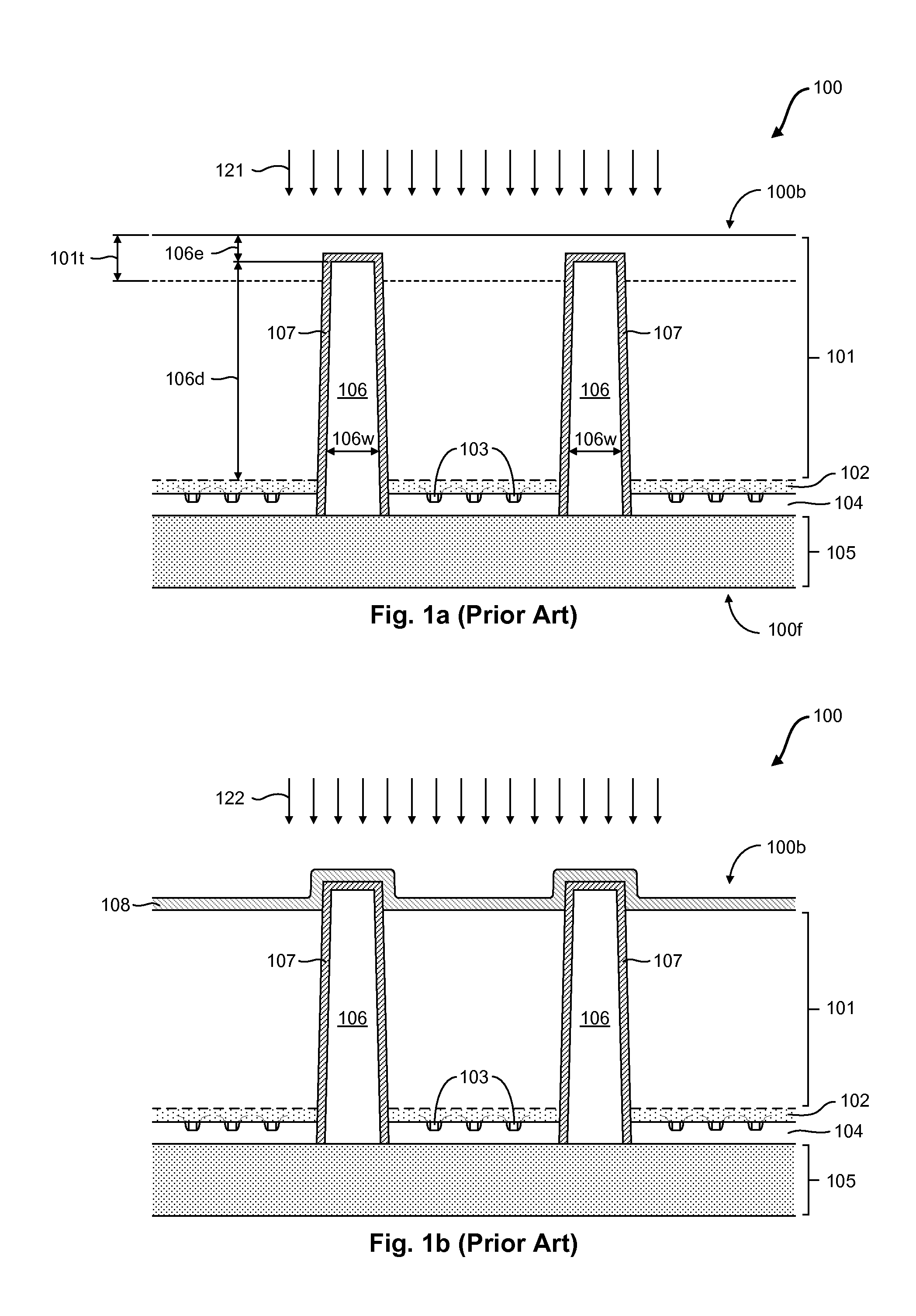
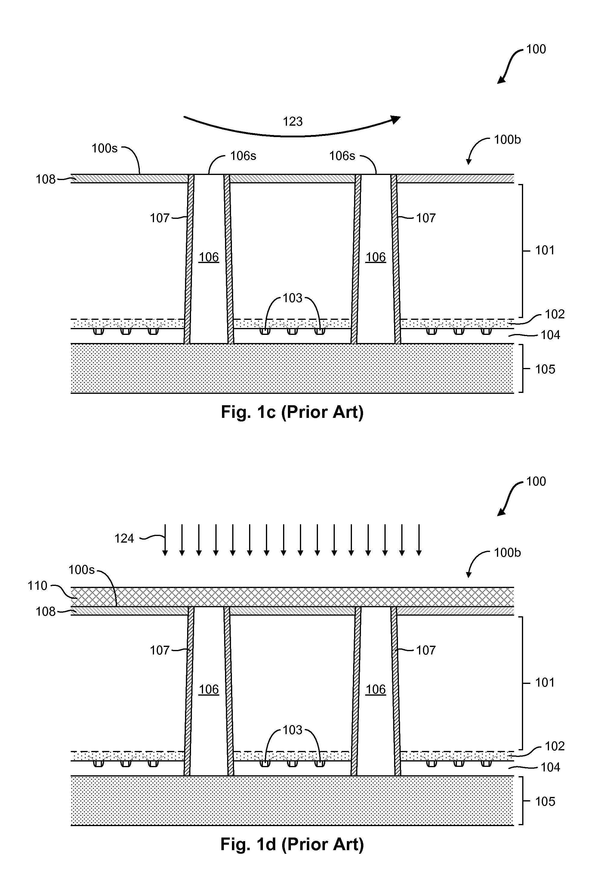
However, as device features are being aggressively scaled, and more semiconductor components are being fit onto the surface of a single chip, the required number of electrical interconnects necessary for circuit functionality dramatically increases, resulting in an overall circuit layout that is increasingly becoming more complex and more densely packed.
Furthermore, even though improvements in photolithography processes have yielded significant increases in the integration densities of 2D circuit designs, simple reduction in feature size is rapidly approaching the limit of what can presently be achieved in only two dimensions.
However, the above described process may impose some limitations on the overall layout of a given chip, and consequently, on the 3D circuit designs.
For most applications utilizing aluminum-based contact pads 110p, RDL process integration commonly requires additional processing steps to form patterned metal lines and additional passivation and / or insulating layers, thus increasing the overall integration complexity and cost.

Method used


Image

  • TSV Backside Processing Using Copper Damascene Interconnect Technology
  • TSV Backside Processing Using Copper Damascene Interconnect Technology
  • TSV Backside Processing Using Copper Damascene Interconnect Technology

Examples


Embodiment Construction

[0032]Various illustrative embodiments of the present subject matter are described below. In the interest of clarity, not all features of an actual implementation are described in this specification. It will of course be appreciated that in the development of any such actual embodiment, numerous implementation-specific decisions must be made to achieve the developers' specific goals, such as compliance with system-related and business-related constraints, which will vary from one implementation to another. Moreover, it will be appreciated that such a development effort might be complex and time-consuming, but would nevertheless be a routine undertaking for those of ordinary skill in the art having the benefit of this disclosure.

[0033]The present subject matter will now be described with reference to the attached figures. Various structures and devices are schematically depicted in the drawings for purposes of explanation only and so as to not obscure the present disclosure with deta...


PUM


Abstract

Generally, the subject matter disclosed herein relates to interconnect structures used for making electrical connections between semiconductor chips in a stacked or 3D chip configuration, and methods for forming the same. One illustrative method disclosed herein includes forming a conductive via element in a semiconductor substrate, wherein the conductive via element is formed from a front side of the semiconductor substrate so as to initially extend a partial distance through the semiconductor substrate. The illustrative method also includes forming a via opening in a back side of the semiconductor substrate to expose a surface of the conductive via element, and filling the via opening with a layer of conductive contact material.

Description

BACKGROUND[0001]1. Field of the Disclosure[0002]Generally, the present disclosure relates to sophisticated integrated circuits, and, more particularly, manufacturing methods for back side processing of through-silicon vias (TSV's) and the resulting interconnect structures.[0003]2. Description of the Related Art[0004]In recent years, the device features of modern, ultra-high density integrated circuits have been steadily decreasing in size in an effort to enhance the overall speed, performance, and functionality of the circuit. As a result, the semiconductor industry has experience tremendous growth due to the significant and ongoing improvements in integration density of a variety of electronic components, such as transistors, capacitors, diodes, and the like. These improvements have primarily come about due to a persistent and successful effort to reduce the critical dimension—i.e., minimum feature size—of components, directly resulting in the ability of process designers to integr...

Claims


Application Information

Patent Timeline
IPC IPC(8): H01L23/498H01L21/768H01L21/28
CPCH01L21/76898H01L23/481H01L2924/00014H01L2224/131H01L2224/05572H01L24/11H01L2224/05552H01L2224/0401H01L2224/05569H01L2224/05008H01L2224/05009H01L2224/0557H01L24/03H01L24/05H01L24/13H01L2224/02372H01L2224/13022H01L2924/014
Inventor LU, YUE KANGYUAN, SHAONINGLIM, YEOW KHENGTAN, JUAN BOON
Owner GLOBALFOUNDRIES SINGAPORE PTE LTD
Learn More