Determination of oil saturation in reservoir rock using paramagnetic nanoparticles and magnetic field
a technology of paramagnetic nanoparticles and magnetic field, applied in the field of oil recovery, can solve the problems of difficult independent estimation, difficult to reliably determine the oil saturation of tracer material balance, and shallow probing depth, and achieve the effect of promoting high salinity toleran
- Summary
- Abstract
- Description
- Claims
- Application Information
AI Technical Summary
Benefits of technology
Problems solved by technology
Method used
Image
Examples
example i
Poly(acrylic acid)114-b-Poly(butyl acrylate)B block copolymer coatings on iron oxide Nanoparticles
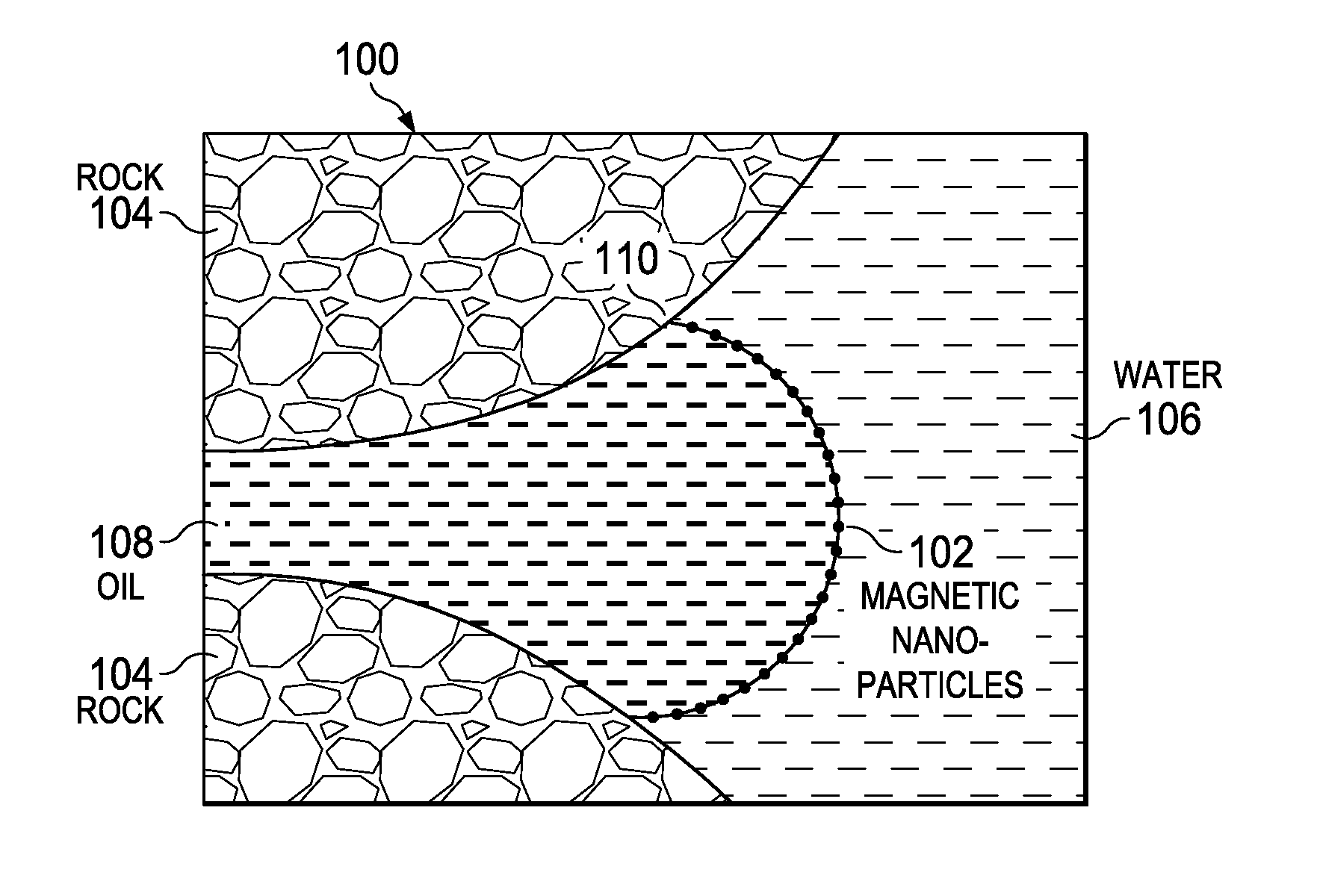
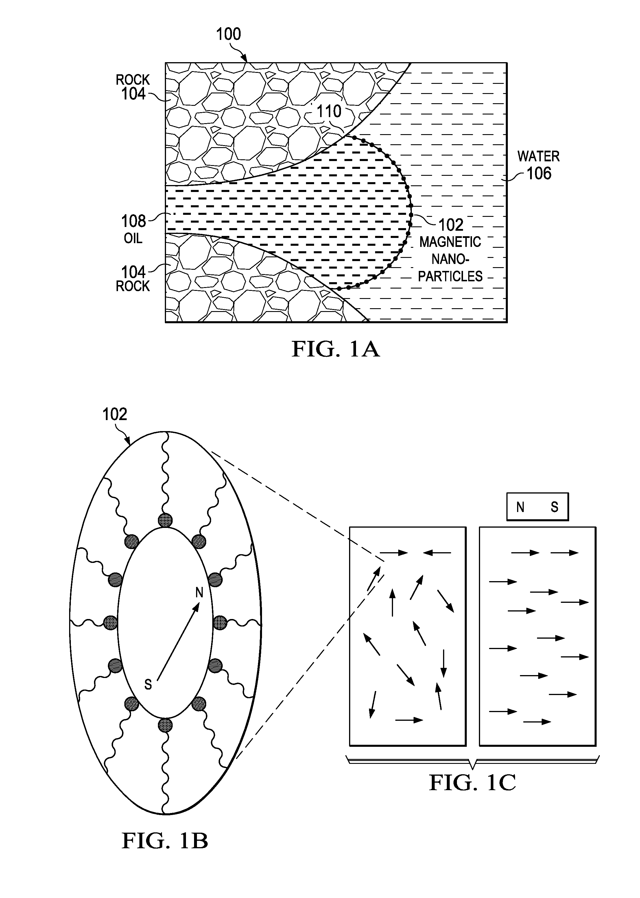
[0148]Iron oxide nanoparticles were synthesized from iron chlorides in the presence of a PAA-b-PBA polymer. This block copolymer was properly balanced to give a high absorption of nanoparticles at the oil / water interface. The inventors used three different ratios of copolymers with a polymer concentration of 2 wt % for the systematic study. Higher hydrophobic ratio showed a higher interfacial tension. The hydrodynamic diameter of the particles was controllable as a function of the reaction concentrations. The results presented herein were obtained with nanoclusters with a diameter on the order of 100 nm. The aqueous dispersions were stable up to 3 wt % salt at pH 8. Therefore, upon intense probe sonication, micron sized oil / water (oil / water) emulsions were formed and with significant stability. Emulsions of water and dodecane with drop sizes down to 5 μm are stabilized with 100 nm inter...
example ii
Poly(acrylic acid)m-r-Poly(butyl acrylate)n Coatings on Iron Oxide Nanoparticles
[0149]The inventors synthesized stable dispersions of small, about 100 nm superparamagnetic iron oxide nanoclusters with high magnetization, and controllable sizes, employing inexpensive random copolymers. In order to achieve these requirements, the inventors introduced random copolymers of Poly(acrylic acid)m-r-Poly(butyl acrylate)n as coating materials on iron oxide nanoparticles. This simple synthesis to apply various ratios of hydrophilic and hydrophobic monomers to design these copolymers allows independent tuning of the molecular weight, attachment density of hydrophobic block, and hydrophobicity of the coatings. A systematic study was performed to relate interfacial activity at the oil-water interface to the copolymer structure. The Fe3O4 particles were produced by co-precipitation of iron chloride salts in aqueous alkaline media with ˜10 nm individual size. The clustering was kinetically controll...
example iii
Poly(4-styrenesulfonic acid-co-maleic acid) Coated Nanoparticles for High Salt Tolerance
[0151]The present inventors also studied the properties of the Poly(4-styrenesulfonic acid-co-maleic acid) coated iron oxide nanoclusters for exceptional salt tolerance (up to 8 wt % salt), higher than that achievable for acrylic-based polymers. The paramagnetic nanoparticles are coated with random copolymers (Saleh, Phenrat et al. 2005) of maleic acid and styrene sulfonic acid, which are suitable for achieving interfacial activities between oil and water. Generally, a random copolymer is usually inexpensive and relatively simple to synthesize. Overall, the method to synthesize the Poly(4-styrenesulfonic acid-co-maleic acid) coated iron oxide nanoclusters has advantages over other procedures in that it is a quick, inexpensive, and a one-step process which is highly reproducible.
[0152]Aqueous dispersions of 0.2 wt % superparamagnetic iron oxide nanoclusters were stabilized with Poly(4-styrenesulfo...
PUM
 Abstract
Description
Claims
Application Information
 - R&D
- Intellectual Property
- Life Sciences
- Materials
- Tech Scout
- Unparalleled Data Quality
- Higher Quality Content
- 60% Fewer Hallucinations
Browse by: Latest US Patents, China's latest patents, Technical Efficacy Thesaurus, Application Domain, Technology Topic, Popular Technical Reports.
© 2025 PatSnap. All rights reserved.Legal|Privacy policy|Modern Slavery Act Transparency Statement|Sitemap|About US| Contact US: help@patsnap.com


