
MEMS microphone with a built-in textile material protecting screen

Active Publication Date: 2013-03-07
SAATI
View PDF3 Cites 8 Cited by
  • Summary
  • Abstract
  • Description
  • Claims
  • Application Information

AI Technical Summary

Benefits of technology

The invention provides a textile material screen that can be applied directly to the microphone during the MEMS making process. This screen protects the MEMS from small particles and water intrusion, while improving its acoustical efficiency. Additionally, this invention allows for the easy buildup of a MEMS in user devices without the need for additional components. The textile screen is composed of materials that have good heat resistance, preventing any damage to the MEMS during soldering operations.

Problems solved by technology

This represents a problem when a protective screen is applied directly at the opening position, as it should be apparent hereinafter.
However, this approach is affected by the serious drawback that it adds an independent component which must be necessarily installed during the device final assembling, thereby increasing the device making time and cost.
Considering the comparatively high number of defective pieces of conventional MEMS making methods, the lack of such a protection in the mentioned assembling steps is very dangerous.
Such a solution is satisfactory, even if not perfect, since a laterally open space is left; however, it has the same drawback as that of the top mounted MEMS systems, that is an additional die-cut portion assembling step and a lack of microphone intermediate protection during the device assembling operation.
The temperature generated in making a MEMS may have a value of 300° C., which is dangerous for the protecting screen material.
This is the main limitation of the prior MEMS making methods, that is a very complex assembling, a lack of protection during the intermediate processing steps and an unsatisfactory and non perfect protection during the use.
As above disclosed, prior approaches are not ideal both for top mounted and bottom mounted MEMS, because of the requirements of assembling an additional component greatly increasing the making cost.
Moreover, the logistic properties are also deteriorated because of the provision of the mentioned additional component to be added and separately handled.
In actual practice, such an idea is impracticable because of temperature limitations.
Thus, by considering the minimum distance and high conductibility of these metal portions, the screen melting temperature is undesirably achieved during the soldering operation.

Method used


Image

  • MEMS microphone with a built-in textile material protecting screen
  • MEMS microphone with a built-in textile material protecting screen

Examples


Embodiment Construction

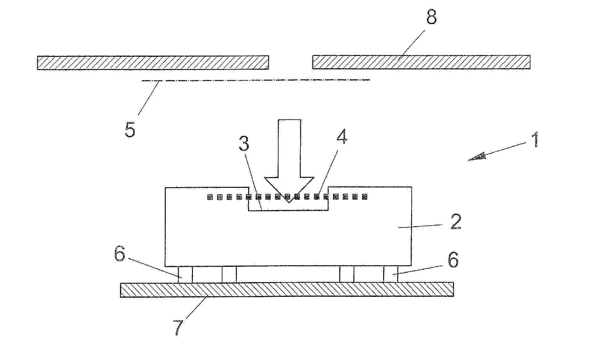
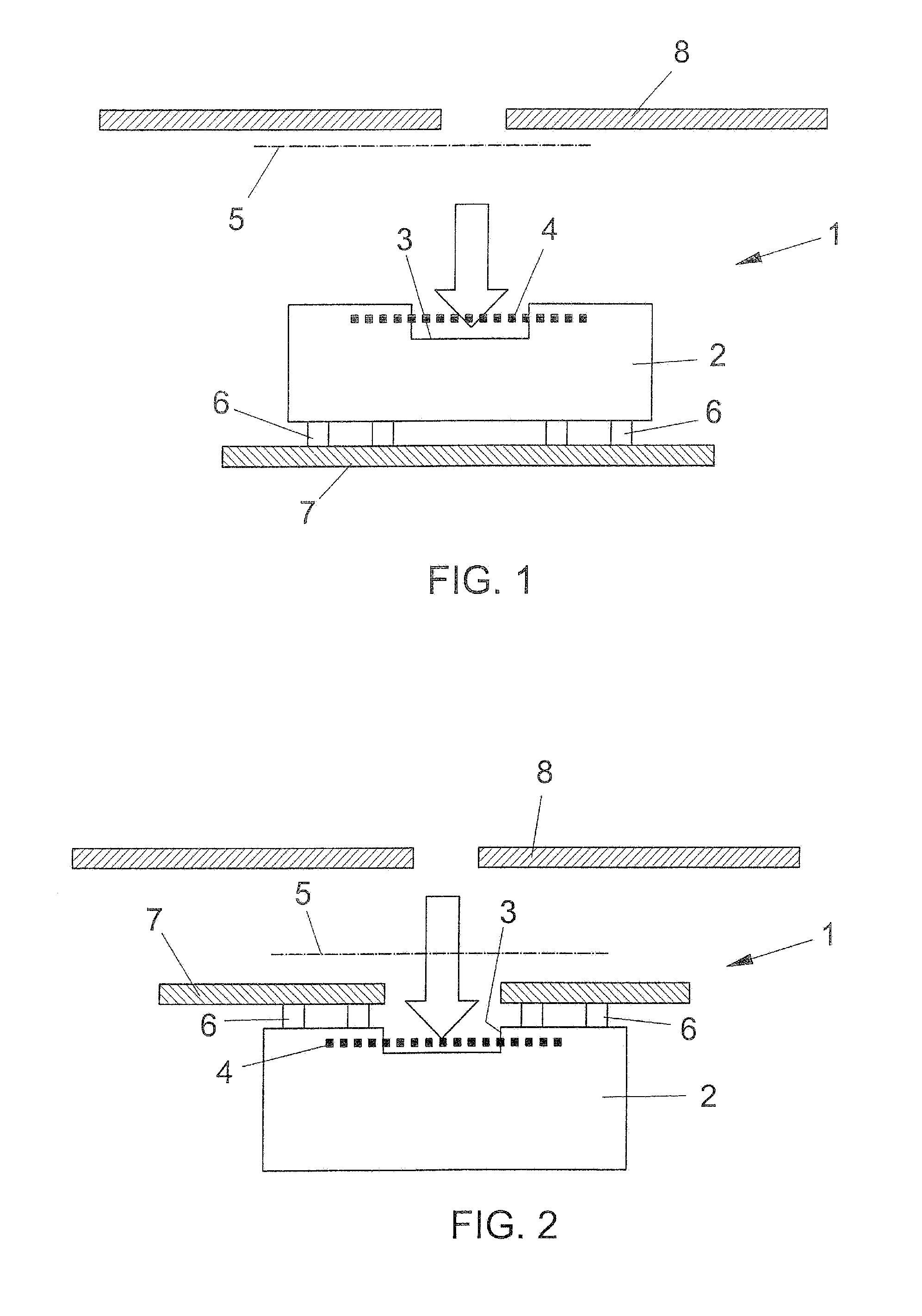
[0075]With reference to the number references of the above mentioned figures, the built-in textile material screen, for protecting a MEMS, according to the present invention, generally indicated by the reference number 1, comprises a microphone body 2 having an opening 3 thereat is arranged a textile screen 4, which is built-in in the microphone body 2 during the “packaging” phase of the MEMS device.

[0076]FIG. 1 shows an application example of the MEMS at a top position thereof.

[0077]More specifically, FIG. 1 shows, by a dash-dot line, indicated the reference number 5, the position of a prior protective screen, applied as an independent die-cut portion.

[0078]On the contrary, the protective screen 4 according to the present invention is associated to the MEMS body 2 and constitutes an integrating part of the latter.

[0079]Accordingly, the microphone and related screen may be processed as an independent component.

[0080]The opening 3 is fully protected against extraneous particles, in a...


PUM


Abstract

A MEMS microphone with a built-in textile material protecting screen comprises a microphone body having an opening thereat is arranged a textile material protecting screen which is built-in in the microphone body, during the production phase of the MEMS device called “packaging”.

Description

BACKGROUND OF THE INVENTION[0001]The present invention relates to a MEMS microphone with a built-in textile material protective screen.[0002]As it is known, the most common types of microphones for acoustical devices are the so-called “ECM” (Electret and Capacitor Microphone) and “MEMS” (Micro Electrical Mechanical System) microphones.[0003]The second microphone type is a small device for installation in cellular phones and other hand-held acoustical devices, and has a typical size of just 7×4×3 mm.[0004]A MEMS microphone comprises a microphone metal body which is made by the so-called “packaging” assembling process, in which different material layers, also comprising metal materials, are overlapped onto one another in a fully automatic manner.[0005]After having soldered the microphone inner electric circuit components, the microphone thus made is separated from a disposable microphone plate, by cutting through the perimeter of the latter.[0006]By a single cutting operation, a plura...

Claims


Application Information

Patent Timeline
IPC IPC(8): H04R1/00
CPCH04R1/086H04R19/04H04R19/005H01L29/84B81C2203/0136
Inventor MIETTA, MARCOCANONICO, PAOLO
Owner SAATI
Learn More