
Method and arrangement for using low-energy source for controlling air temperature in room space

a low-energy source and air temperature technology, applied in lighting and heating apparatus, instruments, heating types, etc., can solve the problems of limited ability of a conventional air-source heat pump to transfer heat energy from the outside air to the room space or a water accumulator, and few solutions have managed to utilise several energy sources. , to achieve the effect of reducing the humidity of the inside air and reducing the consumption of electricity

Inactive Publication Date: 2013-01-03
INS TSTO EJPAN
View PDF6 Cites 3 Cited by
  • Summary
  • Abstract
  • Description
  • Claims
  • Application Information

AI Technical Summary

Benefits of technology

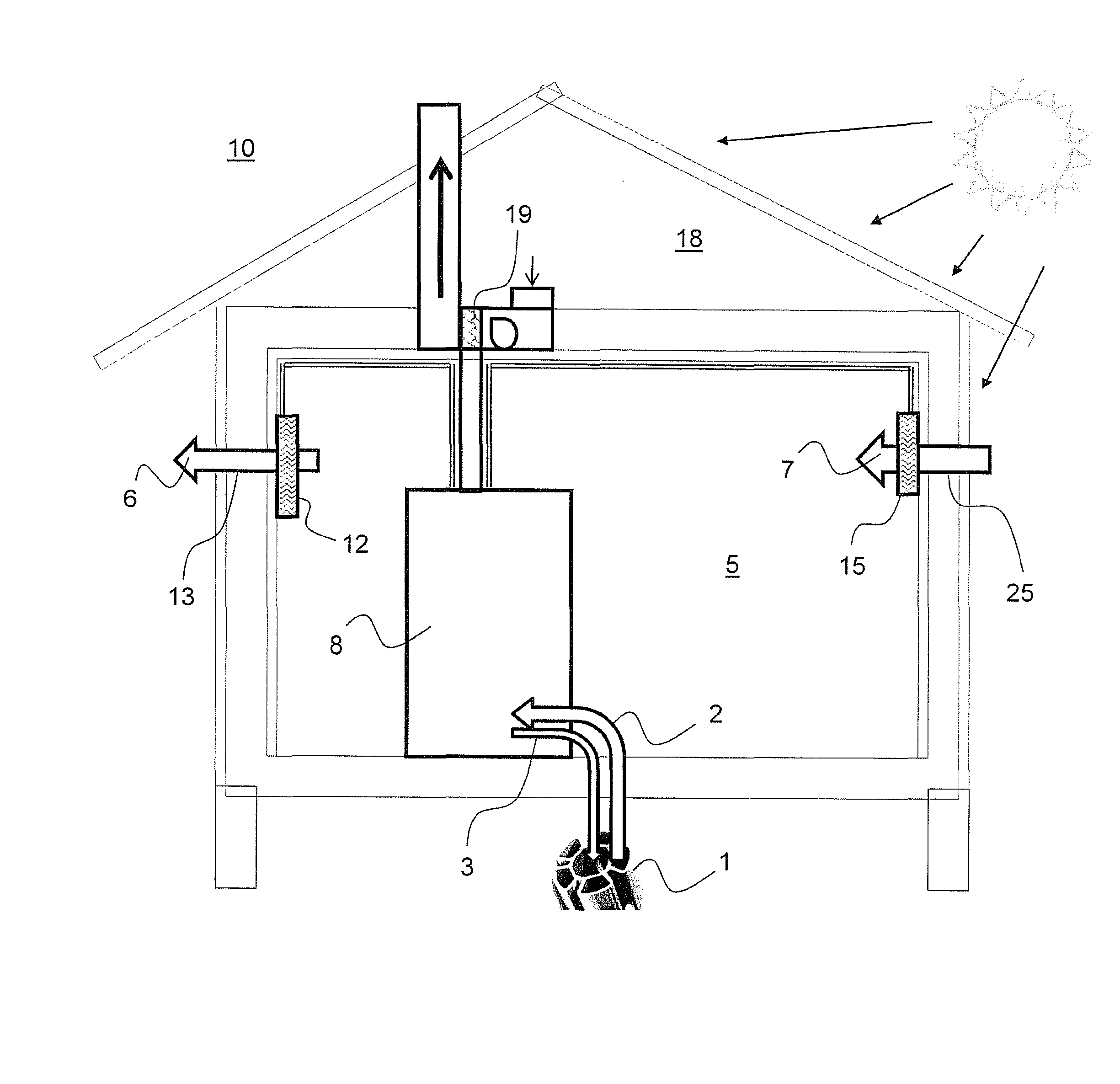
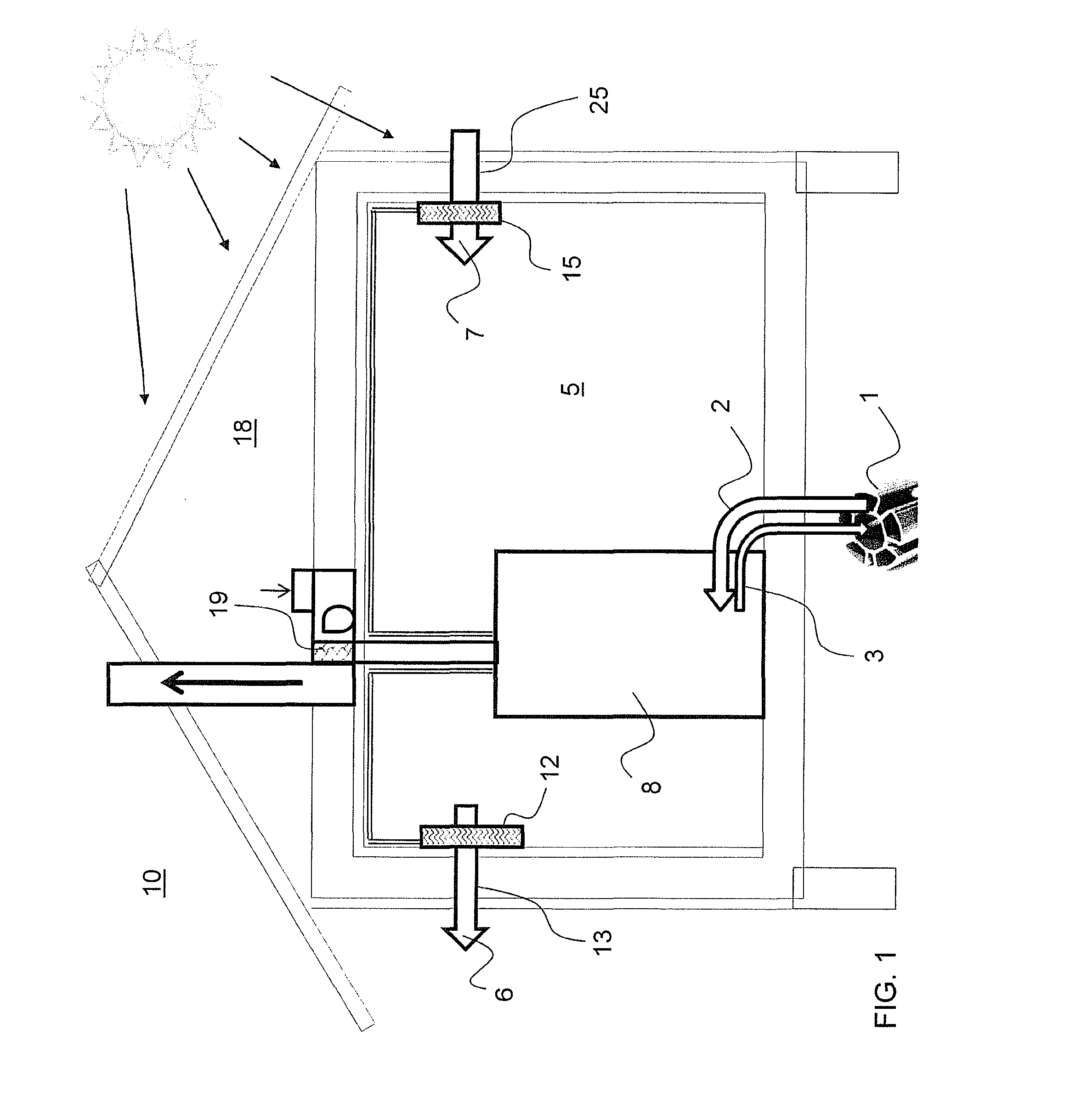
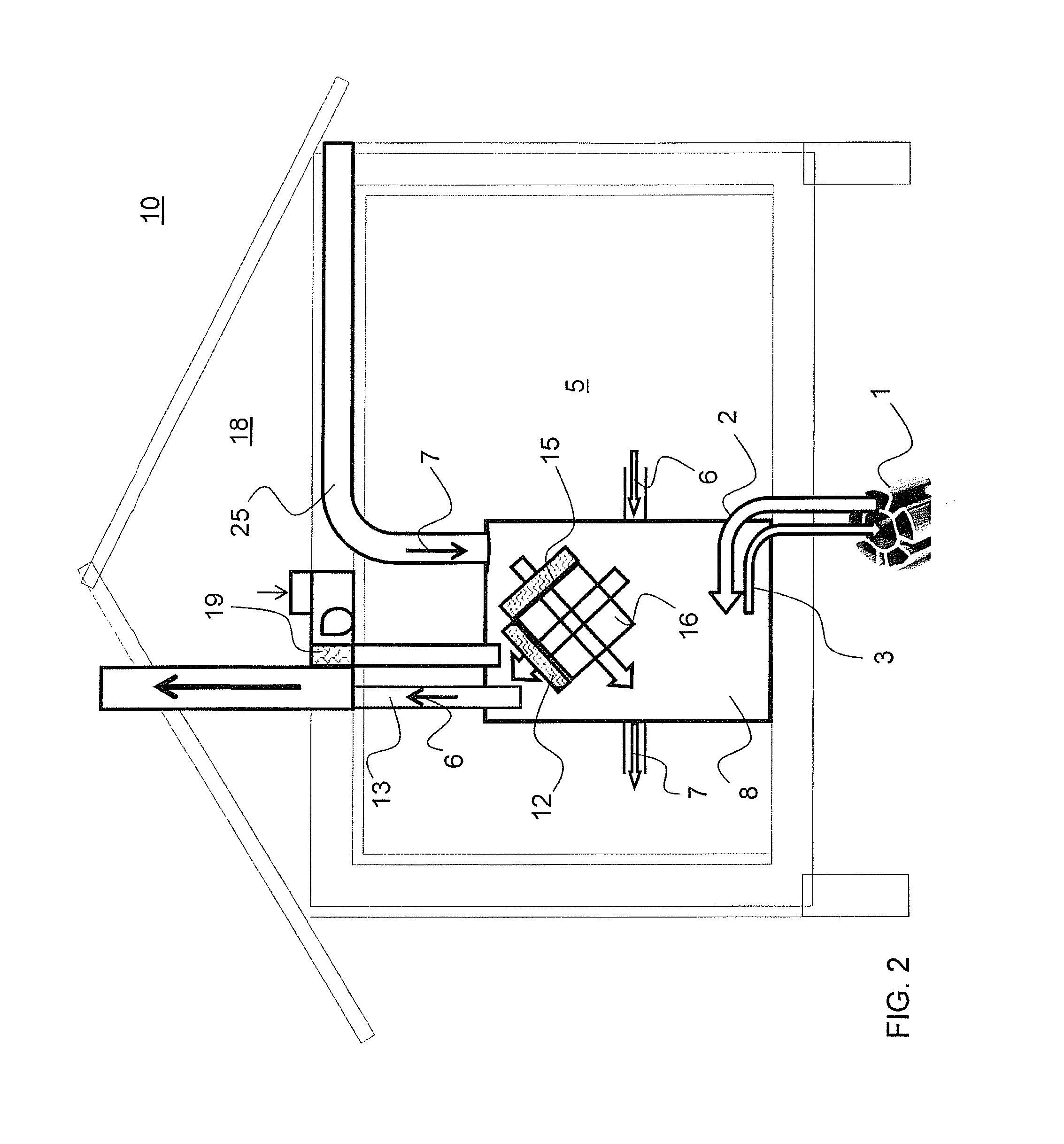
The invention improves the efficiency of heat energy utilization in buildings by allowing the recovered heat energy from air to be used to control the temperature of air being supplied to room spaces. This means that more heat energy can be utilized for controlling the temperature, and there is less demand for electricity. The invention also allows for the use of additional heat from an accumulator if needed. The invention also includes a method to cool and dry the air being supplied to the room spaces, which leads to a reduction in humidity. Overall, the invention improves energy utilization and reduces energy consumption in buildings.

Problems solved by technology

Usually these apparatuses utilise energy from the ground, air or the sun, but only few solutions have managed to utilise several energy sources simultaneously or alternatively.
However, these known solutions have several weaknesses and problems.
The ability of a conventional air-source heat pump to transfer heat energy from the outside air to room spaces or a water accumulator is limited.
On the other hand, an exhaust air heat pump that serves as the only heating device is only effective at temperatures higher than about minus five degrees.
A problem of applying refrigeration technology is the electric power it requires.
A problem of cooling techniques in particular is in most cases how to utilise the electrically produced heat energy.

Method used


Image

  • Method and arrangement for using low-energy source for controlling air temperature in room space
  • Method and arrangement for using low-energy source for controlling air temperature in room space
  • Method and arrangement for using low-energy source for controlling air temperature in room space

Examples


second embodiment

[0039]This second embodiment of the method may also be implemented in such a manner that the flow of heat transfer liquid supplied from the extraction circuit 1 is divided into two or more paths of the supply circuit 2. In this manner, the rate of the heat transfer liquid circulating in the heat source can be doubled or multiplied without having to have larger heat collection and releasing devices in the extraction circuit. The heat transfer liquid circulated by the extraction circuit pump 4 is thus distributed to two or more transfer pipes when it comes from the heat source to the supply circuit. In this case, the liquid radiator 12 recovering the heat from the flow of air 6 to be removed from the room space and the heating circuit 14 of the accumulator 9 of the heat exchanger means 8 are two separate flow circuits in the arrangement according to the method.

[0040]In the embodiment of FIG. 4, for instance, the heat energy transferred from the flow of air 6 to be removed from the roo...

third embodiment

[0042]In the present arrangement according to FIGS. 5 and 6, heat energy is recovered from the additional energy source 17 by, for example, supplying air flow 20 by means of a blower 21 from, in this embodiment, the attic of the building to a preferably insulated duct 22 and the above-described liquid radiator 19 therein that circulates the heat transfer liquid. In this procedure, the blower leading the air flow is preferably heat-regulated in such a manner that it operates with full power when the temperature of the air flowing in the duct and supplied from the attic is above +5° C., and the power becomes constantly lower until the air temperature is −10° C., at which point the blower stops. When the blower stops, a damper 23 mounted in the duct 22 blocks the flow route and prevents the air flow from causing the freezing of the heat transfer liquid in the liquid radiator 19 of the duct.

[0043]When, on the other hand, the temperature of the liquid radiator 19 in the duct 22, circulat...


PUM


Abstract

The present invention relates to a method and arrangement for using a low-energy source for controlling the air temperature in a room space (5). In the invention, the ratio of the desired inside air temperature in the room space (5) to the outside air (10) temperature is compared. Furthermore the temperature of a heat transfer liquid coming from an extraction circuit (1) is determined. On the basis of these detected temperature levels, heat energy of the heat transfer liquid is regulated, if necessary, after which the heat transfer liquid is channelled to a supply air radiator (15) controlling the temperature of air (7) to be supplied to the room space (5) in order to control this air temperature. At the end of the circulation, the heat transfer liquid is channelled via a return circuit (3) of means back to the extraction circuit (1).

Description

BACKGROUND OF THE INVENTION[0001]The present invention relates to a method according to the preamble of claim 1 for using a low-energy source for controlling the air temperature in a room space. The invention also relates to an arrangement according to the preamble of claim 8 for performing such a method.[0002]Apparatuses for heating, cooling and ventilation, which utilise the available energy sources only to a limited extent, are previously known. Usually these apparatuses utilise energy from the ground, air or the sun, but only few solutions have managed to utilise several energy sources simultaneously or alternatively.[0003]Particularly interesting in this context are heating and cooling systems based on refrigeration techniques, which have been used in different forms for decades. Refrigeration apparatuses may be used for removing and transferring excess heat from a room space to the outside. The room space may also be heated with these apparatuses, when the refrigeration appara...

Claims


Application Information

Patent Timeline
Patent Type & Authority Applications(United States)
IPC IPC(8): G05D23/00F24D11/00
CPCF24D11/0214Y02B30/126F24D2200/11F24D2200/22F24F5/0046F24F12/006F24F2005/0053F24F2005/0064Y02B10/20Y02B10/24Y02B10/40Y02B10/70Y02B30/52Y02B30/563F24D11/0242Y02A30/272Y02B30/56F24F12/002
Inventor PANULA, ERKKI-JUSSI
Owner INS TSTO EJPAN
Learn More