
Multi-layer micro/nanofluid devices with bio-nanovalves

a nano-nanofluidic and multi-layer technology, applied in the field of micro/nanofluidic devices and systems, can solve the problems of extremely limited mass flow rate, and achieve the effect of economic, effective and efficien

Inactive Publication Date: 2013-01-03
UCHICAGO ARGONNE LLC
View PDF0 Cites 3 Cited by
  • Summary
  • Abstract
  • Description
  • Claims
  • Application Information

AI Technical Summary

Benefits of technology

This design enables efficient nanofluidic flow and mixing at the nanoscale, achieving high mass flow rates and precise control, overcoming the limitations of traditional devices by using microfluidic pressure drops to drive nanofluidic flow, and allowing for applications such as drug delivery and biochemical reactions.

Problems solved by technology

Given high pressure loss in nanoscale fluidic flow, the mass flow rate can be extremely limited by the strength of the inventive device.

Method used


Image

  • Multi-layer micro/nanofluid devices with bio-nanovalves
  • Multi-layer micro/nanofluid devices with bio-nanovalves
  • Multi-layer micro/nanofluid devices with bio-nanovalves

Examples


Embodiment Construction

[0066]The following is a detailed description and explanation of the preferred embodiments of the invention and best modes for practicing the invention.

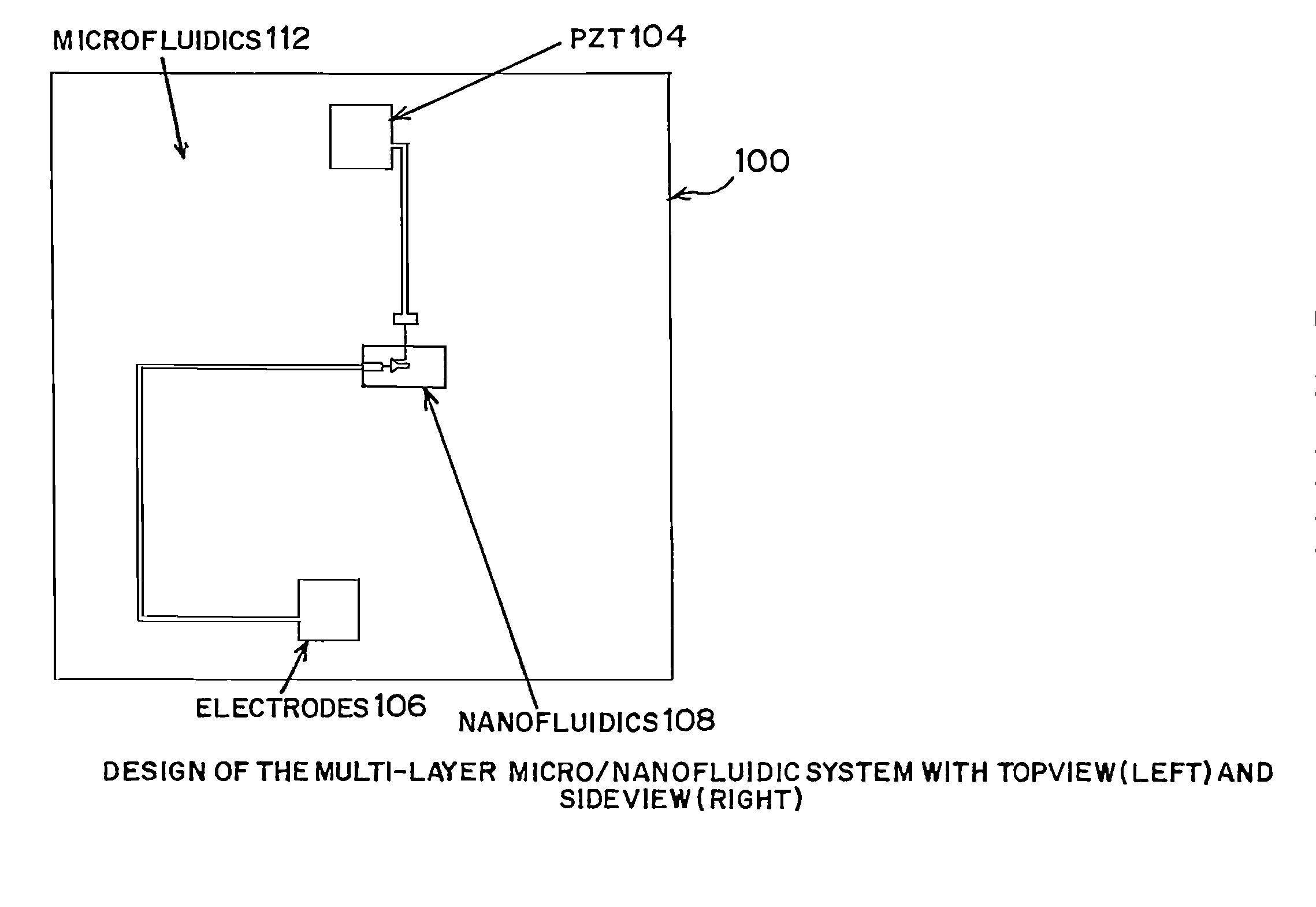
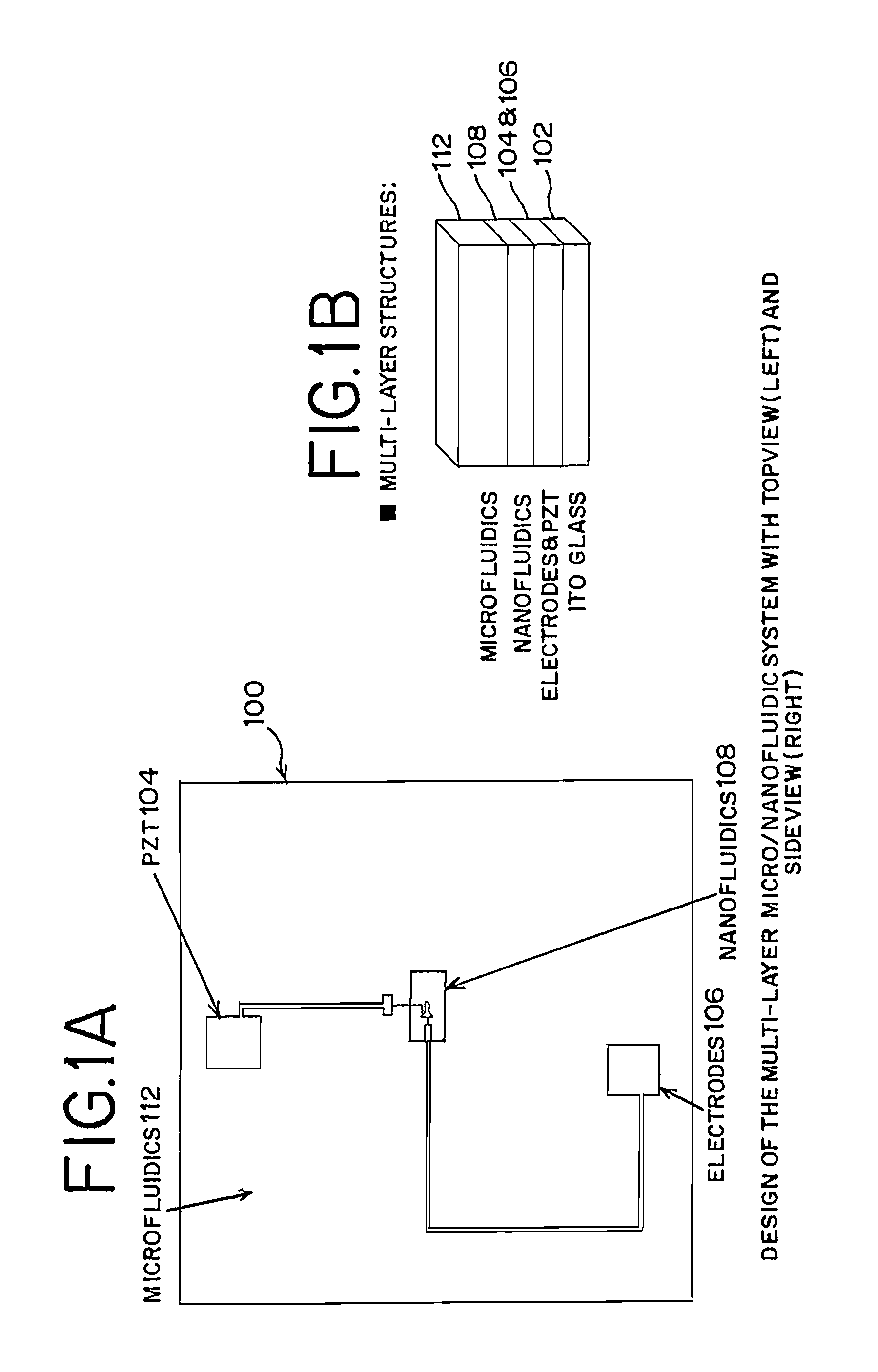
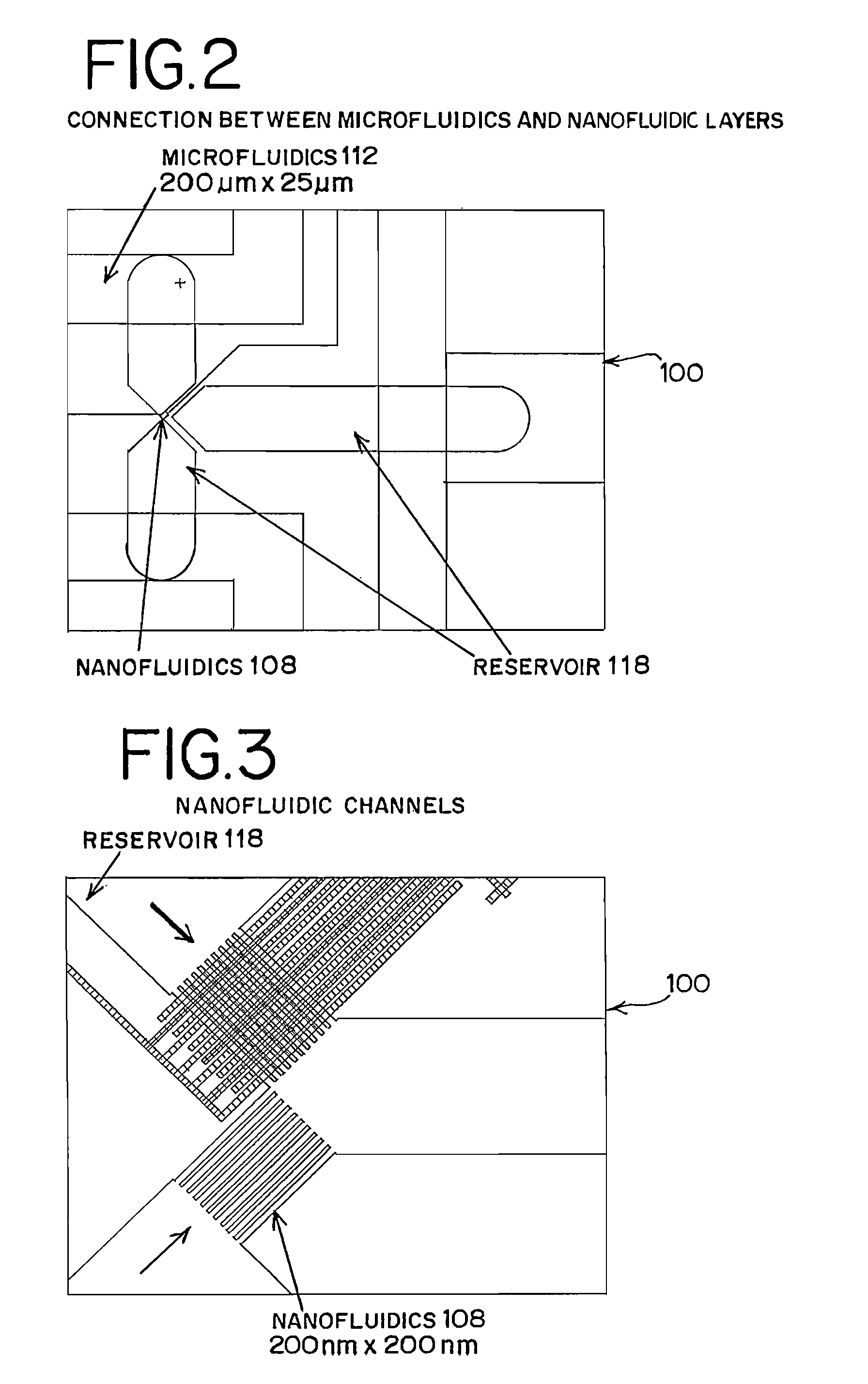
[0067]As shown in the drawings, a novel, multi-layer micro / nanofluidic flow device 100 (FIGS. 1A and 1B) is provided, which is also referred to as a multi-layered nanofluidic flow device. The multi-layer micro / nanofluidic flow device can comprise a substrate 102 made of indium tin oxide coated glass (ITO glass) upon which is stacked and positioned a layer 104 of lead zirconate titanate (Pb(ZrxTii-x)O3) (PZT). The multi-layer micro / nanofluidic flow device contains electrodes 106 connected to the PZT. A nanofluidics layer (nanofluidics) 108 with nanochannels 110 is stacked and positioned upon the PZT layer. A microfluidics layer (microfluidics) 112 with microchannels 114 is stacked and positioned upon the nanofluidics layer. Bio-nanovalves (biomolecular nanovalves) 116 in the nanochannels are activated by polarization of the PZT layer....


PUM

PropertyMeasurementUnit
fluid flow ratesaaaaaaaaaa
spacing distanceaaaaaaaaaa
widthaaaaaaaaaa

Abstract

A user-friendly multi-layer micro / nanofluidic flow device and micro / nano fabrication process are provided for numerous uses. The multi-layer micro / nanofluidic flow device can comprise: a substrate, such as indium tin oxide coated glass (ITO glass); a conductive layer of ferroelectric material, preferably comprising a PZT layer of lead zirconate titanate (PZT) positioned on the substrate; electrodes connected to the conductive layer; a nanofluidics layer positioned on the conductive layer and defining nanochannels; a microfluidics layer positioned upon the nanofluidics layer and defining microchannels; and biomolecular nanovalves providing bio-nanovalves which are moveable from a closed position to an open position to control fluid flow at a nanoscale. The micro / nano fabrication process for fabricating a multi-layer micro / nanofluidic flow device can comprise: forming a conductive layer on a substrate; forming an electrode pattern; forming a nanofluidics layer with a nanochannel pattern to define nanochannels; forming a microfluidics layer with a microchannel pattern to define microchannels; and assembling the microfluidics layer on the nanofluidics layer. The micro / nano fabrication process can include: synthesizing a thin film of PZT on ITO glass, electron beam lithography, sputtering, spin-coating, photolithography, and plasma treatment.

Description

CROSS REFERENCES TO RELATED APPLICATION[0001]This application is based upon U.S. Provisional Patent Application No. 61 / 032,509 filed Feb. 29, 2008.STATEMENT REGARDING FEDERALLY SPONSORED RESEARCH OR DEVELOPMENT[0002]The United States Government has rights in this invention pursuant to Contract No. LDRD 2006-269-NO and Contract No. DE-ACO2-06CH11357 between the U.S. Department of Energy (DOE) and UChicago Argonne, LLC representing Argonne National Laboratory.BACKGROUND OF THE INVENTION[0003]This invention relates to micro and nanofluidic devices and systems, and more particularly, to a multi-layer micro / nanofluidic flow device and micro / nano fabrication process.[0004]Microfluidic devices and systems have attracted the attention of researchers due to high surface-to-volume ratio and improved performance in physical, chemical, biochemical, biological analysis and applications, especially enhancing the efficiency of chemical reaction, bio-analysis, and mass / momentum / heat transport in sh...

Claims


Application Information

Patent Timeline
Patent Type & Authority Applications(United States)
IPC IPC(8): F15C1/00B05D3/06
CPCB01L3/50273B01L3/502738F16K99/0003F16K99/0042B01L2200/027B01L2300/0867B01L2300/0874B01L2300/0896B01L2400/0415B01L2400/0487B01L2400/0627B01L2400/0633F16K2099/0073Y10T137/206B01F33/301
Inventor LI, HAOOCOLA, LEONIDAS E.AUCIELLO, ORLANDO H.FIRESTONE, MILLICENT A.
Owner UCHICAGO ARGONNE LLC
Learn More