
Piezoelectric thin film, piezoelectric element, and manufacturing method thereof

a piezoelectric element and thin film technology, applied in piezoelectric/electrostrictive transducers, generators/motors, device material selection, etc., can solve the problem of low piezoelectricity, the inability to obtain sufficient piezoelectric strain from bfo, and the environmental impact of the lead component considered a problem, etc. problem, to achieve good piezoelectricity

Active Publication Date: 2012-12-20
CANON KK +1
View PDF11 Cites 15 Cited by
  • Summary
  • Abstract
  • Description
  • Claims
  • Application Information

AI Technical Summary

Benefits of technology

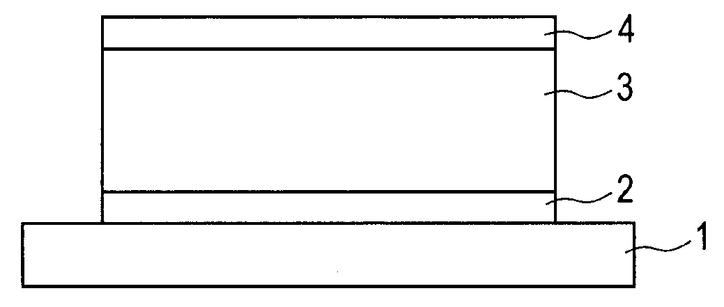
[0012]The present invention has been made to deal with the above-mentioned problem, and provides a piezoelectric thin film having good piezoelectricity in which a rhombohedral structure and a tetragonal structure are mixed.
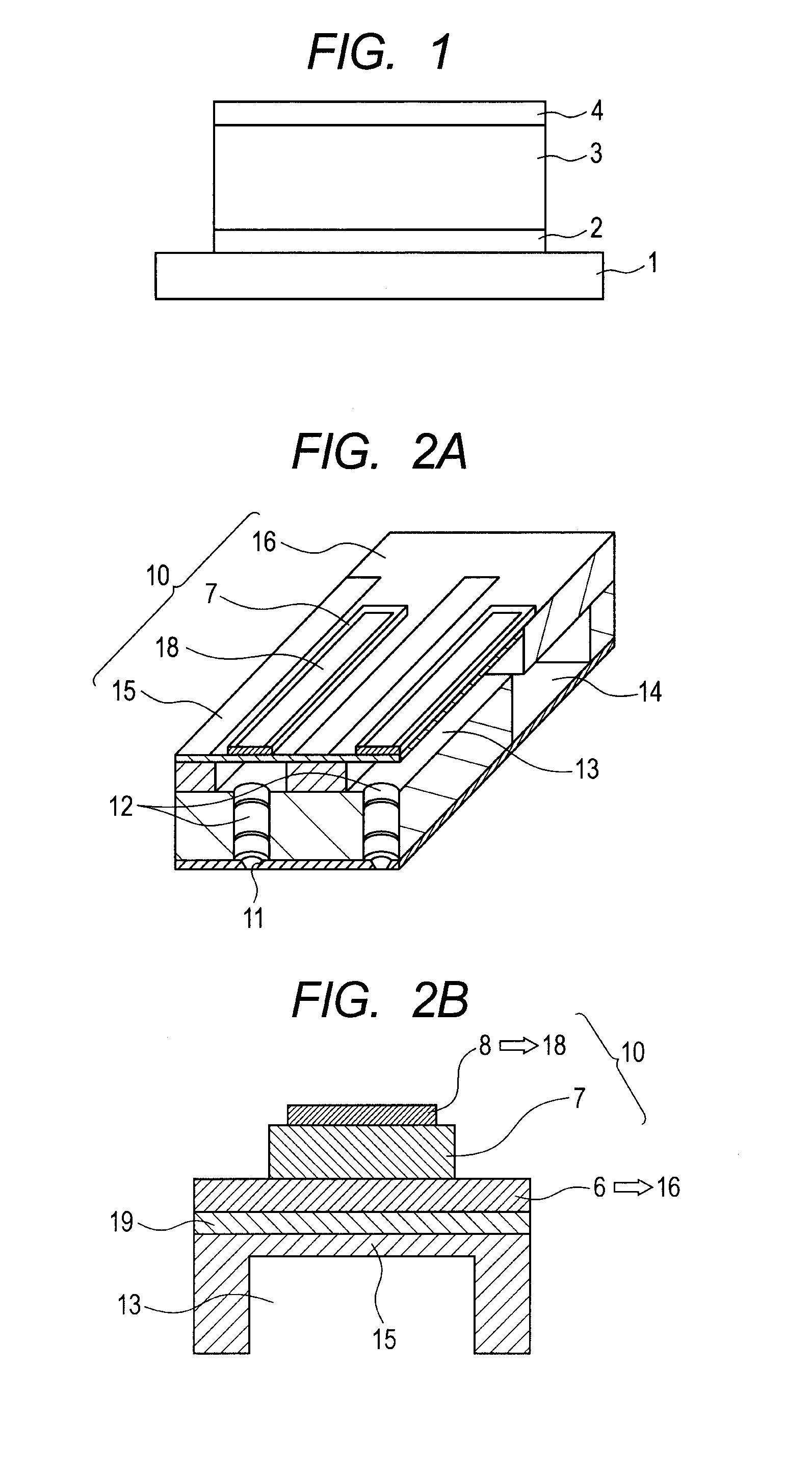
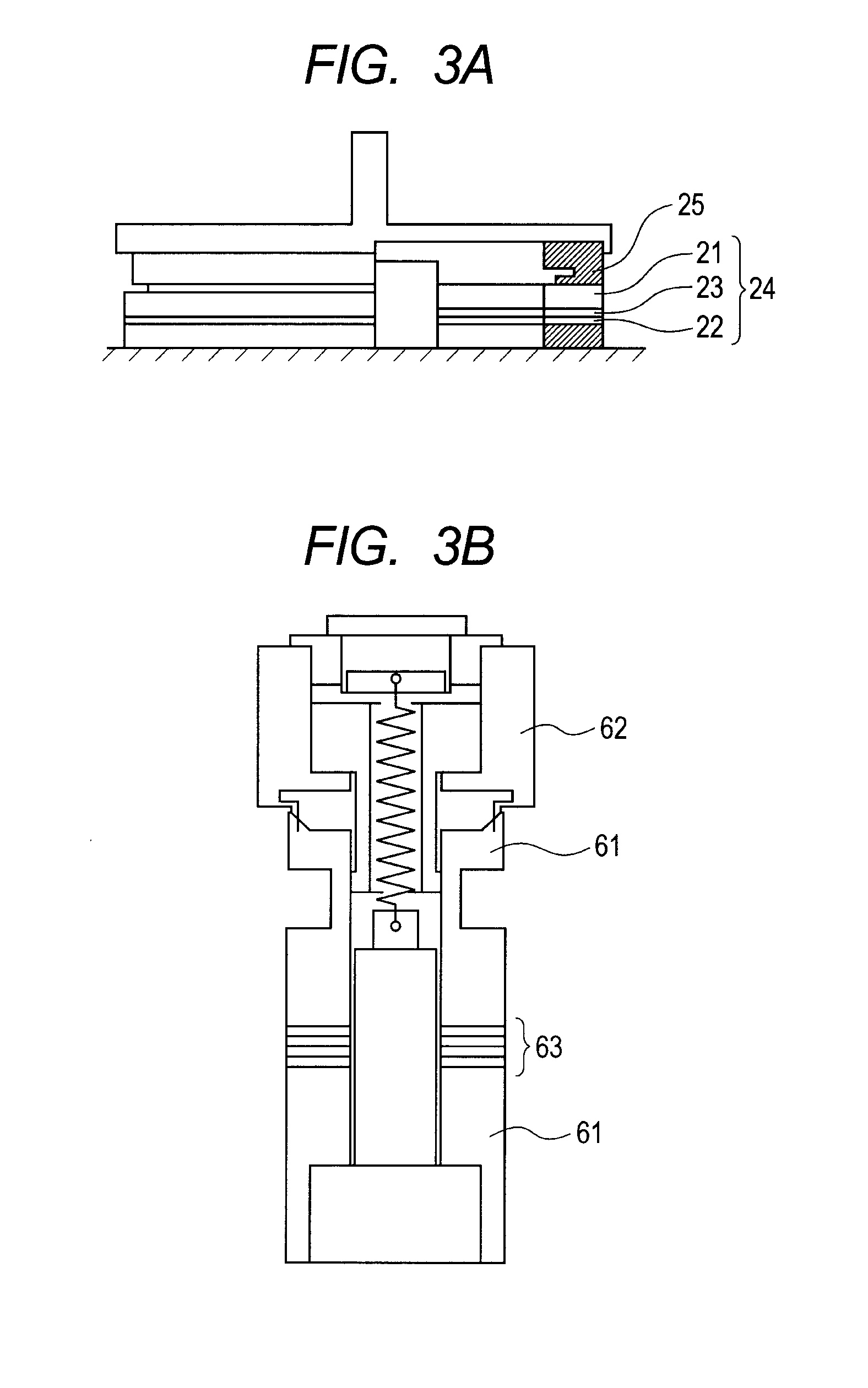
[0019]According to the present invention, the piezoelectric thin film having good piezoelectricity can be provided. Further, the present invention can provide the piezoelectric element including the above-mentioned piezoelectric thin film, the manufacturing method for the piezoelectric element, the liquid discharge head, and the ultrasonic motor.

Problems solved by technology

Therefore, the environmental impact of the lead component is considered to be a problem.
However, there remains a problem that sufficient piezoelectric strain cannot be obtained from BFO.
In the conventional method of manufacturing a BFO thin film, however, impurity phases other than the perovskite structure are increased with the substitution of Co, which causes a problem of low piezoelectricity.
However, there is a small volume difference between a unit cell of the pseudo-rhombohedral phase and a unit cell of the pseudo-tetragonal phase, with the result that sufficient piezoelectric strain have not been obtained so far.

Method used


Image

  • Piezoelectric thin film, piezoelectric element, and manufacturing method thereof
  • Piezoelectric thin film, piezoelectric element, and manufacturing method thereof
  • Piezoelectric thin film, piezoelectric element, and manufacturing method thereof

Examples


example 1

[0130]A piezoelectric thin film made of a perovskite type metal oxide was formed by a chemical solution deposition method using the precursor solution of Manufacture Example 1 shown in Table 1 and the substrate A with electrodes shown in Table 2.

[0131]First, the precursor solution was applied to the surface of the substrate with a spin coater (3000 rpm). The applied layer was heat-treated at 250° C. for 5 minutes to dry the solvent. The heat treatment process was performed with an electric dryer under an air atmosphere.

[0132]Hereinafter, in the same manner as in the foregoing, the applying step and the drying step were repeated to form second to twentieth layers. Finally, the entire substrate having the multiple applied layers was placed in an infrared-annealing tube furnace. An oxygen gas was introduced into the tube furnace via a commercially available, industrial ozone generator at a flow rate of 1 L / min (corresponding to an oxygen concentration in the furnace of 50 vol % to 80 v...

examples 2 to 13

[0138]The piezoelectric thin films according to the present invention were each formed in the same manner as in Example 1 except that the precursor solution, the substrate, the number of coatings, the crystallization atmosphere, and the crystallization temperature were changed. Table 3 shows the manufacture conditions of each example.

[0139]In Example 13, the crystallization was performed at 430° C. in a tube furnace in which an oxygen gas was introduced at a flow rate of 1 L / min. The oxygen gas was not introduced via an ozone generator.

[0140]XRD measurement showed that each of the piezoelectric thin films had a mixed crystal system of a tetragonal structure selectively (001) oriented and a rhombohedral structure selectively (100) oriented. The amount of impurity phases other than a perovskite type structure was extremely small. Further, it was confirmed from the shift in peak position in XRD that Co was introduced in a perovskite skeleton.

[0141]Further, evaluations were carried out ...


PUM

PropertyMeasurementUnit
Temperatureaaaaaaaaaa
Thicknessaaaaaaaaaa
Thicknessaaaaaaaaaa

Abstract

Provided are a piezoelectric thin film having good piezoelectricity in which a rhombohedral structure and a tetragonal structure are mixed, and a piezoelectric element using the piezoelectric thin film. The piezoelectric thin film includes a perovskite type metal oxide, in which the perovskite type metal oxide is a mixed crystal system of at least a rhombohedral structure and a tetragonal structure, and a ratio between an a-axis lattice parameter and a c-axis lattice parameter of the tetragonal structure satisfies 1.15≦c / a≦1.30. The piezoelectric element includes on a substrate: the above-mentioned piezoelectric thin film; and a pair of electrodes provided in contact with the piezoelectric thin film.

Description

TECHNICAL FIELD[0001]The present invention relates to a piezoelectric thin film, a piezoelectric element, a manufacturing method for the piezoelectric element, a liquid discharge head, and an ultrasonic motor. In particular, the present invention relates to a lead-free piezoelectric thin film with piezoelectricity improved by control of the crystal structure.BACKGROUND ART[0002]A piezoelectric element is typically formed of a bulk-shaped or film-shaped piezoelectric material including a lower electrode and an upper electrode.[0003]As a piezoelectric material, ABO3 type ceramics such as lead zirconate titanate (hereinafter, referred to as “PZT”) is generally used.[0004]However, PZT contains lead at an A-site of a perovskite skeleton. Therefore, the environmental impact of the lead component is considered to be a problem. In order to address this problem, a piezoelectric material using a lead-free perovskite type metal oxide has been proposed.[0005]A typical lead-free piezoelectric ma...

Claims


Application Information

Patent Timeline
IPC IPC(8): H01L41/18H01L41/22B41J2/045B41J2/055B41J2/135B41J2/14B41J2/16C04B35/00H01L41/08H01L41/09H01L41/187H01L41/29H01L41/316H01L41/317H01L41/39H02N2/00
CPCB41J2/14233H01L41/0478H01L41/081Y10T29/42H01L41/318H02N2/106H02N2/163H01L41/1878H10N30/878H10N30/2047H10N30/8561H10N30/078H10N30/706H10N30/85H10N30/01
Inventor KUBOTA, MAKOTOTAKEDA, KENICHIHAYASHI, JUMPEISHIMADA, MIKIOSHIMAKAWA, YUICHIAZUMA, MASAKINAKAMURA, YOSHITAKAKAWAI, MASANORI
Owner CANON KK
Learn More