
System, apparatus, and method for closed tube sampling and open tube sampling for automated clinical analyzers

a clinical analyzer and automated technology, applied in the field of system, apparatus, and method of closed tube sampling and open tube sampling for automated clinical analyzers, to achieve the effects of reducing operator risks, reducing throughput, assay performance, and reducing labor requirements for sorting, balancing and centrifugation

Inactive Publication Date: 2012-12-06
ABBOTT LAB INC
View PDF11 Cites 32 Cited by
  • Summary
  • Abstract
  • Description
  • Claims
  • Application Information

AI Technical Summary

Benefits of technology

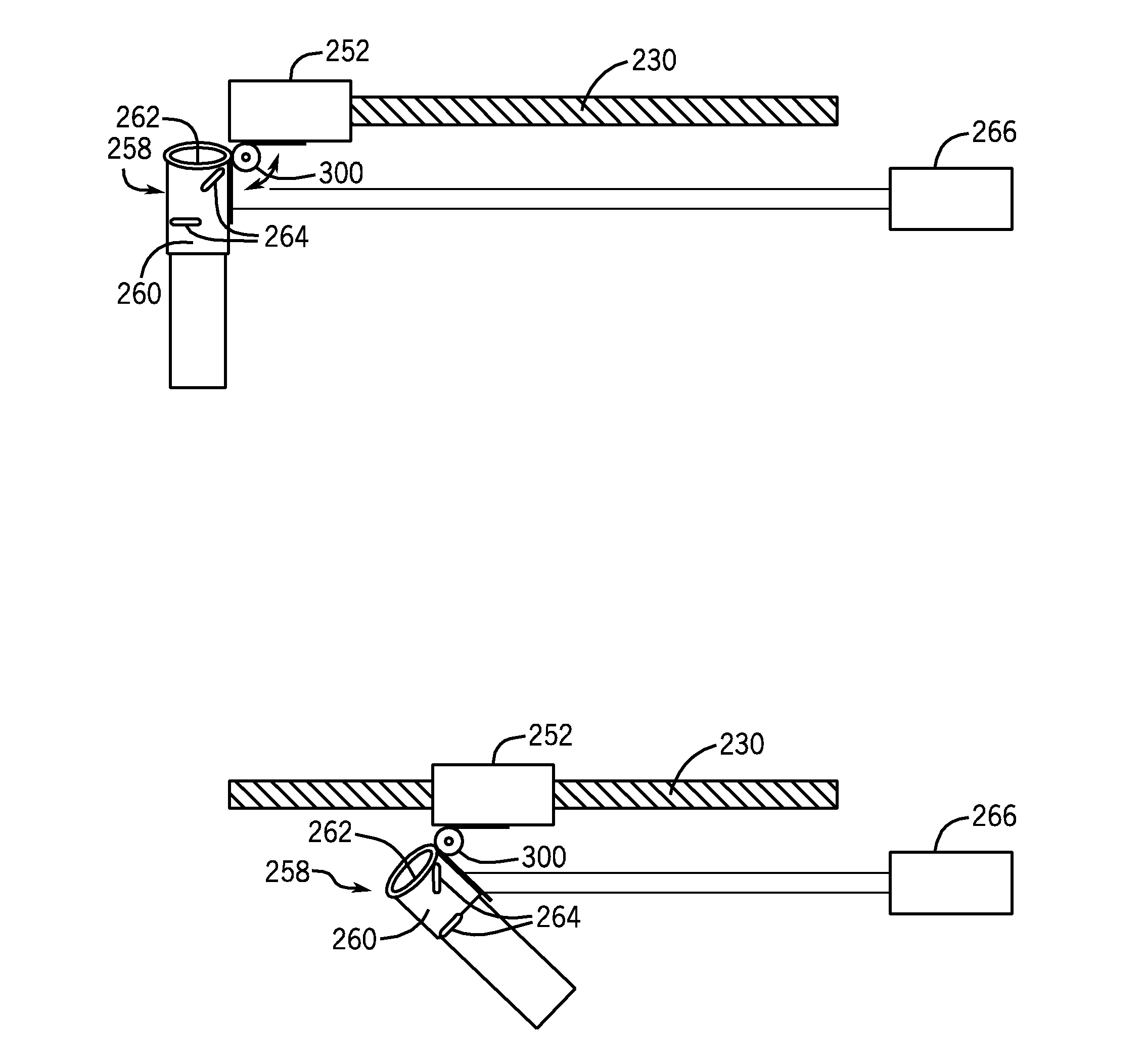
[0037]In another embodiment, a balancing weight is used to balance the centrifuge. The balancing weight is attached to and supported by a first positioning mechanism, and the combination of the balancing weight and the first positioning mechanism is further attached to and supported by a second positioning mechanism, the second positioning mechanism supported by the carousel of the centrifuge. The positioning mechanisms can be moved in the appropriate directions to move the balancing weight to cancel any imbalance generated by rotation of the centrifuge.
[0044]The system described herein reduces risks to operators, without reducing throughput, assay performance, and without exposing the operators to cuts brought about by cutting openings in stoppers of sample tubes. Such risks include, but are not limited to, repetitive motion injury, exposure to biological hazards, and exposure to aerosols.
[0045]The integration of hematology testing, immunoassay testing, and clinical chemistry testing reduces the labor required for sorting, balancing, and centrifugation and significantly reduces the time needed to obtain a result by integrating the step for separating blood into the system containing the clinical analyzers. The system described herein provides a fully automated method for processing one sample in one sample tube that can be used for hematology testing, immunoassay testing, and clinical chemistry testing, while providing high throughput for large laboratories that process large numbers of samples, employ random and continuous access assay processing, as well as assays for STAT samples. In addition, these benefits can be realized with the current hematology analyzers, immunoassay analyzers, and clinical chemistry analyzers, such as, for example, “ARCHITECT” immunoassay analyzers, “ARCHITECT” clinical chemistry analyzers, and “CELL-DYN” hematology analyzers, without requiring the development of new analyzers. The system provides a variety of concepts for designing various laboratory environments without requiring significant changes.
[0046]Integration of hematology, immunoassay, clinical chemistry testing requires only one sample tube for testing, thereby reducing distress to the patient, the cost of collecting samples, the cost of inventory (to stock more than one type of sample tube), and the cost of disposing of solid waste.
[0047]The continuous access feature of the centrifuge described herein eliminates delays due to “batches”, and consequently, any subsequent delays for processing STAT samples.
[0048]The continuous access centrifuge described herein enables the centrifuge to receive energy from mechanical sources, such as hand cranks, bicycles, windmills, waterwheels, etc., thereby allowing modern centrifugation steps to be carried out in developing countries.

Problems solved by technology

Most current laboratories are not highly automated and use assays that are monitored closely and controlled for quality.
Insufficient dilution may allow formation of small clots that lower cell counts; excessive dilution can cause cells to shrink or swell.
Second even relatively large blood samples do not provide a sufficient quantity to flow through an analyzer for measurement.
1. Impedance principle: This is the coulter principle based on the fact that blood cells are poor conductors of electricity. Coulter counters count cells as they flow, in single file, through an aperture in an electric field. As each cell crosses the aperture, the increase in electrical impedance is proportional to the cell's size. The cells are uniformly suspended in a diluent, and the suspension passes through the aperture at a constant rate. Because these counters discriminate between particles according to size, their thresholds (usually aperture size) can be set to the preferred size limit, depending on the cells to be counted. Dilutions for white blood cell count are critical. Because these cells are small and numerous, samples with high white blood cell counts may exceed the counting capacity of the instrument or may cause high coincidence counts—that is counts in which two cells pass through the aperture simultaneously. An increased amount of diluent may be needed to avoid these errors, or an instrument may automatically correct for these errors.2. Optical principles: Automated systems are based on flow-through (also called flow cytometer) optical technologies that identify cells on the basis of their fluorescent labeling ability. Blood cells in a diluent pass through an aperture, scattering a focused light beam. Cells diffract (scatter) light in a manner that is measurable and unique to each cell type. Accuracy can be influenced by coincidence errors—two cells passing through the aperture may be measured as one large cell (primary coincidence) or two particles that are below the measurement threshold may be counted as one cell (secondary coincidence). In most cases, the coincidence factor is too small to distort the count significantly. Most instruments automatically correct for coincidence errors.
Testing blood samples in a laboratory exposes operators to biological hazards, including aerosols.
In addition, when operators remove stoppers from closed sample tubes, repetitive motion can lead to physical injuries, such as carpal tunnel syndrome.
Laboratories that test blood samples expend substantial labor to sort sample tubes for hematology or immunoassay / clinical chemistry testing.
These operations add a minimum of 10 minutes or more to time needed to obtain a result, and could delay an assay of a STAT sample by an additional 10 minutes.
Testing blood samples in a laboratory requires a substantial amount of labor to sort sample tubes for hematology testing, immunoassay testing, or clinical chemistry testing.

Method used


Image

  • System, apparatus, and method for closed tube sampling and open tube sampling for automated clinical analyzers
  • System, apparatus, and method for closed tube sampling and open tube sampling for automated clinical analyzers
  • System, apparatus, and method for closed tube sampling and open tube sampling for automated clinical analyzers

Examples


example 1

Operation of a Closed Tube Sampling System

[0202]A versatile embodiment of a closed tube sampling system includes one hematology analyzer, one immunoassay analyzer, one clinical chemistry analyzer, one sample tube aspirating module, and an agglutination reagent addition module. See FIG. 9. An operator loads sample tube carriers holding sample collection tubes having stoppers and containing samples of whole blood that have not undergone centrifugation. The robotic sample handler prioritizes carriers holding sample collection tubes for STAT assays ahead of carriers containing sample collection tubes for routine assays. The barcode reader of the closed tube sampling system reads the barcodes on the sample collection tubes, detects the presence of stoppers on the sample collection tubes, if any, the stoppers on the sample collection tubes (if required), and transfers a specified volume of sample to an aliquot tube. The sample tube carrier can then be removed from the system. The sample i...

example 2

Operation of a Closed Tube Sampling System

[0205]FIG. 9 illustrates an embodiment of a closed tube sampling system that has one hematology analyzer, one immunoassay analyzer, one clinical chemistry analyzer, and one sample tube aspirating module.

[0206]In order to operate the system, the operator of the system loads sample tube carriers having sample collection tubes having stoppers and containing uncentrifuged samples of whole blood. The robotic sample handler prioritizes sample tube carriers holding sample collection tubes for STAT assays ahead of sample tube carriers containing sample collection tubes for routine assays. A barcode reader reads the barcodes on the sample collection tubes, detects the presence of stoppers on the sample collection tubes, if any, a piercing element pierces the stoppers on the sample collection tubes (if required) or a cutting blade cuts slits in the stoppers (if required), and a specified volume of sample is transferred to an aliquot tube. The sample t...

example 3

Operation of a Closed Tube Sampling System

[0209]FIG. 9 illustrates an embodiment of a closed tube sampling system that includes one hematology analyzer, one immunoassay analyzer, one clinical chemistry analyzer, one sample tube aspirating module, and a continuous access centrifugation module. In order to operate the system, the operator loads sample tube carriers holding sample collection tubes having stoppers and containing uncentrifuged samples of whole blood. The robotic sample handler prioritizes sample tube carriers holding sample collection tubes for STAT samples ahead of sample tube carriers holding sample collection tubes for routine analyses. A barcode reader reads the barcodes on the sample collection tubes, detects the presence of stoppers on the sample collection tubes, if any, a piercing element pierces the stoppers of the sample collection tubes (if required) or a cutting blade forms slits in the stoppers (if required), and a specified volume of sample is transferred t...


PUM

PropertyMeasurementUnit
Angleaaaaaaaaaa
Angleaaaaaaaaaa
Weightaaaaaaaaaa

Abstract

A centrifuge to which sample tubes can be introduced while the centrifuge is in motion. The centrifuge comprises a carousel having an upper portion and a lower portion. The upper portion of the carousel has a plurality of positions for sample tubes for a centrifugation operation, a plurality of drive mechanisms attached to the upper portion of the carousel, a movable element mounted upon each drive mechanism, the movable element capable of traversing the length of the drive mechanism when the drive mechanism is actuated, a sample tube-holding assembly comprising a sample tube holder and a bearing attached to each movable element, and at least one balancing element capable of contributing to a force vector that cancels an imbalance vector generated by rotation of the centrifuge.

Description

BACKGROUND OF THE INVENTION[0001]1. Field of the Invention[0002]This invention involves a system for preparing biological samples for automated diagnostic analyses.[0003]2. Discussion of the Art[0004]A centrifuge is a piece of equipment that puts an object in rotation around a fixed axis, applying a force perpendicular to the axis. A centrifuge is generally driven by an electric motor. The centrifuge works using the sedimentation principle, where the centripetal acceleration causes more dense substance to separate out along the radial direction (the bottom of the tube). Simultaneously, lighter objects will tend to move to the top of the tube.[0005]Protocols for centrifugation typically specify the amount of acceleration to be applied to the sample, rather than specifying a rotational speed such as revolutions per minute. This distinction is important because two rotors with different diameters running at the same rotational speed will subject samples to different accelerations. Duri...

Claims


Application Information

Patent Timeline
IPC IPC(8): G01N33/00B04B9/14G01N30/96B01D21/26B26B9/02B04B5/02B04B7/06
CPCB04B5/0421B04B9/146G01N2035/00504B04B2011/046B04B11/04B01D21/262B04B7/12
Inventor FRITCHIE, PATRICK P.
Owner ABBOTT LAB INC
Learn More