Vapor absorption system

a technology of vapor absorption and system, which is applied in the field of system and method of absorption of vapor, can solve the problems of vapor absorption system being used in applications, relatively slow process, and limited application of absorption process

Inactive Publication Date: 2012-11-15
ABARIDY
View PDF4 Cites 2 Cited by
  • Summary
  • Abstract
  • Description
  • Claims
  • Application Information

AI Technical Summary

Benefits of technology

[0010]According to a preferred feature of the invention, the absorption of vapor within the system is effective to cause production of more vapor.
[0025]According to the preferred embodiment, the venturi pump has a venturi throat section configured to receive the gas from the evacuation chamber and the fluid flow is the primary liquid so that the venturi pump is operative to cause the reduced pressure of the gas in the evacuation chamber by receiving the gas into the primary liquid.
[0042]According to a further aspect, the invention resides in a heat transfer system comprising an evacuation chamber adapted to receive a first liquid, at least one venturi vacuum pump associated with the evacuation chamber to cause, in use, the pressure within the evacuation chamber to be reduced to promote vaporization of liquid in the chamber and to thereby cause cooling, and a first heat exchanger having a fluid pathway for a heat exchange fluid to pass through the first heat exchanger and being associated with the evacuation chamber to provide heat to the first liquid in the chamber to support the vaporization and thereby to cool the heat exchange fluid.
[0043]According to a preferred feature of the invention, vapor from the vaporization of the first liquid is received and condensed within a flow stream of a second liquid which passes through the at least one venturi vacuum pump to cause the reduced pressure.

Problems solved by technology

They are usually relatively slow process unless some chemical reaction is occurring.
Because of this, absorption processes have relatively limited application.
However, the present invention has identified a method of obtaining a much faster rate of absorption where chemical interaction is not involved, with the result that vapor absorption systems may be used in applications where they were never previously considered, or at least not considered viable.
It is used often where traditional filtration techniques have not been effective at purifying a liquid mixture.
While conventional distillation is generally effective at purifying liquids such as water, the energy cost is substantial and often uneconomic.
Improvements to the process have increased efficiency significantly, but the process has remained too expensive for purification of water for general use.
However, such systems have had limited success due to difficulty and expense associated with an evacuating system in conjunction with the evaporation and condensing subsystems.
It was particularly applicable to a marine environment but retained some complexity in that it still incorporated a condenser.

Method used


Image

  • Vapor absorption system
  • Vapor absorption system
  • Vapor absorption system

Examples


first embodiment

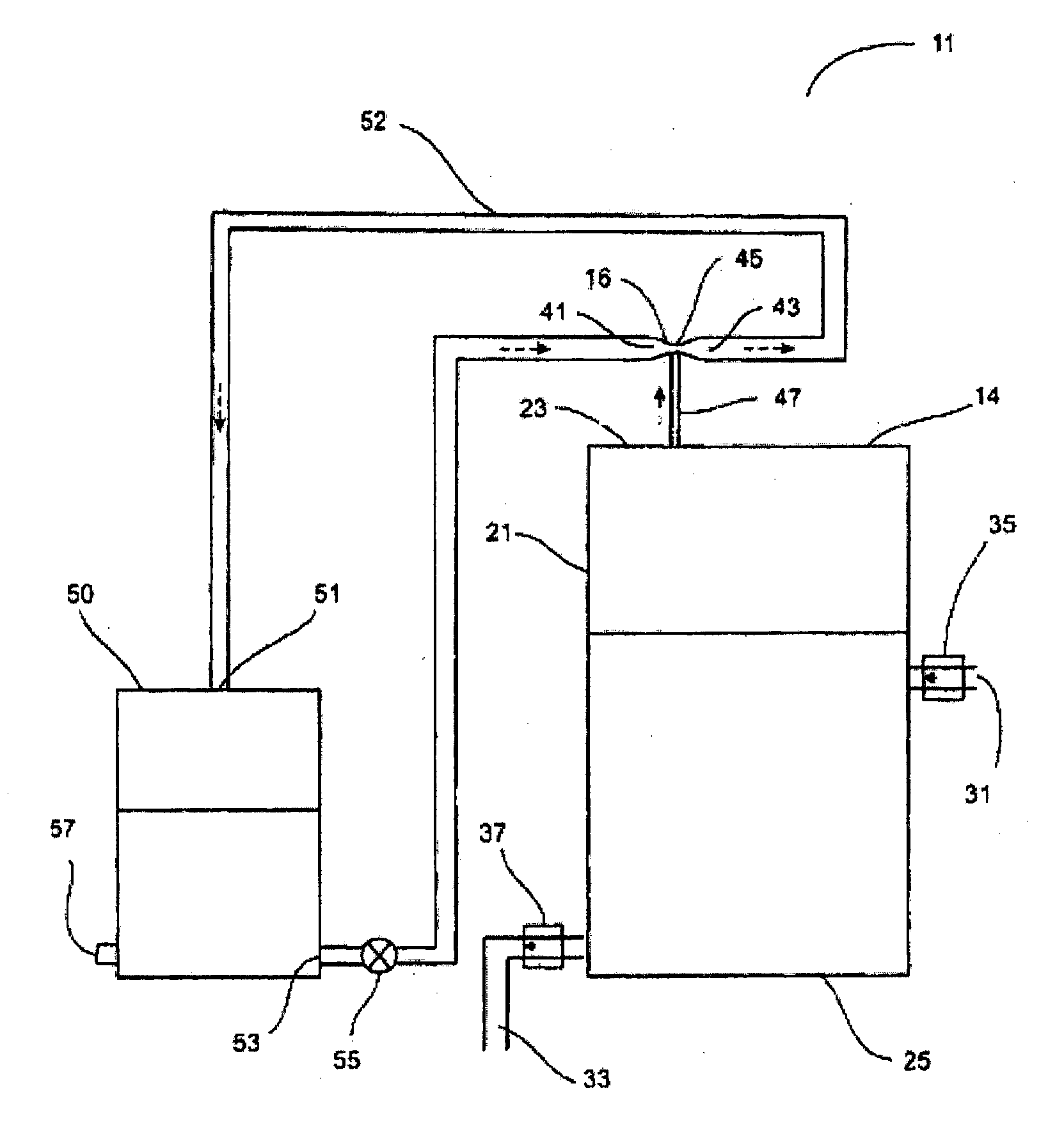
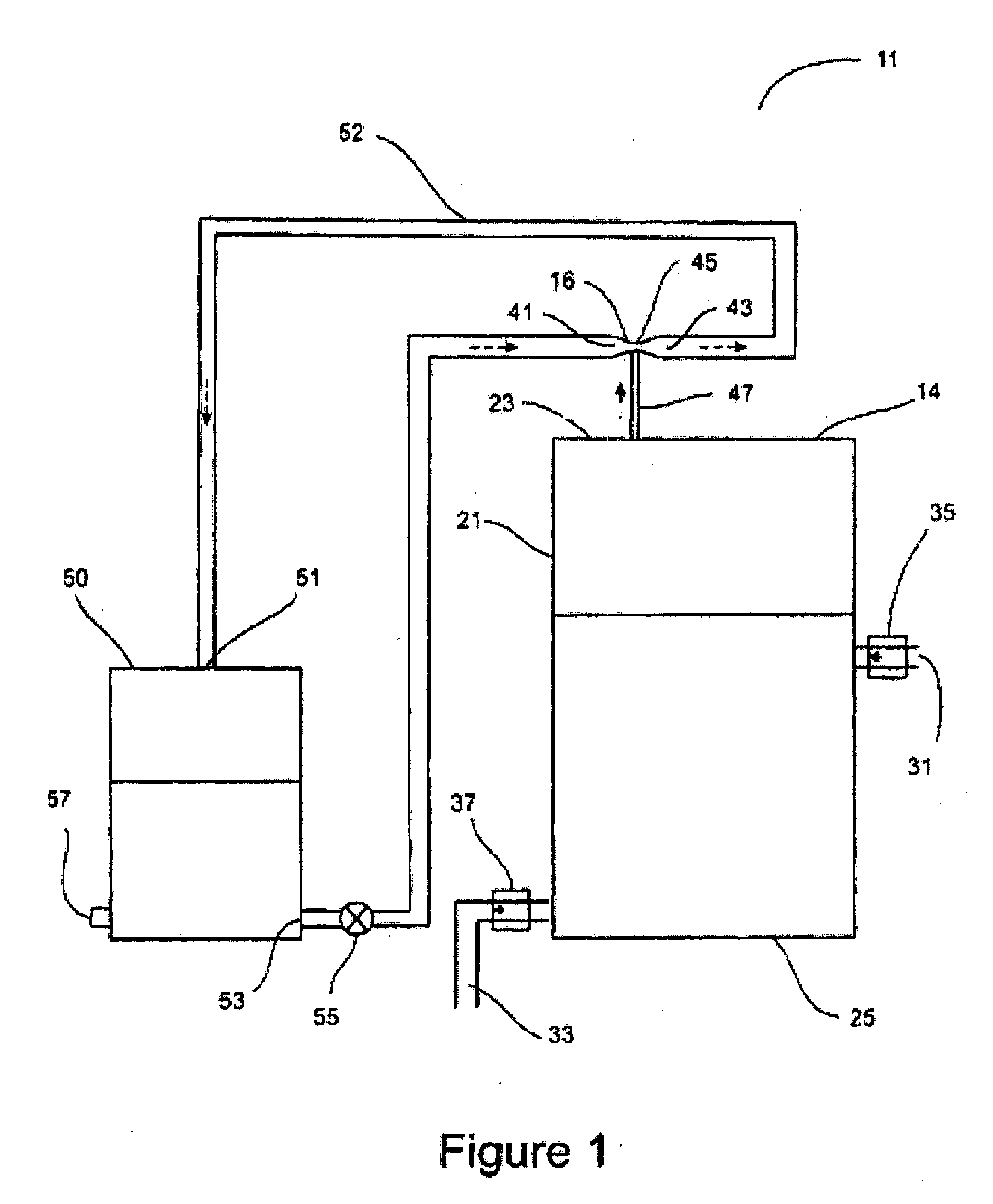
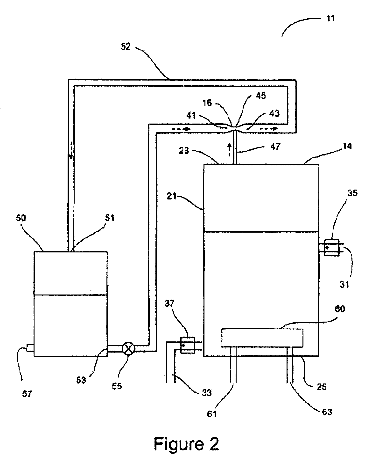
[0059]the invention is directed to a distillation system which incorporates an evacuation chamber and an evacuation pump. The embodiment is described with reference to FIG. 1.

[0060]The distillation system 11 according to the first embodiment comprises an evacuation chamber 14 adapted to receive a quantity of liquid to be distilled. For the purposes of this description, the embodiment will be described with reference to the distillation of water, referred to herein as secondary water, such as contaminated water or ground water which is too polluted or mineralized for direct use, but reference will be made later in the description to the distillation of other mixtures including liquid mixtures. The evacuation chamber 14 is adapted to be evacuated to a reasonably high level (preferably less than 3 kPa) by one or more evacuation pumps 16 and therefore is constructed accordingly. The actual design of the evacuation chamber is not critical to the invention, and will depend significantly u...

second embodiment

[0069]In some locations, secondary water is available that is already at or above the desired operating temperature of the secondary water. In these circumstances, the latent heat may be provided simply by having a controlled, continuous flow of secondary water through the evacuation chamber at a rate somewhat above the rate of evaporation of vapor. This arrangement has the added advantage that the level of concentration of the salts in the secondary chamber is kept at a stable level which is not substantially higher than that of the incoming secondary water. This will significantly reduce the build-up of salt deposits in the evacuation chamber and therefore reduce the maintenance requirements of the chamber. For this latter reason, continuous flow of the secondary water will be preferred even where the secondary water is too cool, and additional heating must be added, as in the In a sophisticated adaptation, a feedback control system is incorporated to regulate the flow of seconda...

third embodiment

[0076]In a further adaptation of the third embodiment, a filtration means is provided at the vapor entry into the venturi to remove any liquid droplets and return them to the secondary water, thereby avoiding contamination of the primary water. This water is not returned to the venturi and therefore the heat rise due to release of latent heat upon the absorption and condensation of the vapor does not affect the operation of the venturi.

[0077]While development of the improved vacuum pumps is in its infancy and many parameters of the configuration will vary the performance, it is believed that there may be a maximum optimal size for larger applications. If that is so, it is possible to operate a plurality of venturis in parallel to remove a higher volume of vapor. The invention is therefore scalable from small domestic units to large systems suitable for reticulated supplies of cities.

[0078]It will be appreciated that the second embodiment may be modified in a manner similar to the ad...


PUM


Abstract

Provided herein is a vapor absorption system, adapted to receive a vapor comprising a vacuum pump having an operating liquid, where the vapor is received by an operating liquid and condensed therein to provide condensed liquid mixed with the operating liquid.

Description

CROSS-REFERENCE[0001]This application claims the benefit of U.S. Provisional Application No. 61 / 433,165 filed Jan. 14, 2011, and U.S. Provisional Application No. 61 / 443,705, filed Feb. 16, 2011, which applications are entirely incorporated herein by reference.BACKGROUND OF THE INVENTION[0002]The present invention relates to a system and method for absorption of a vapor into a liquid. The system has many applications but is particularly useful for distillation of a liquid mixture such as water with impurities. It also has application as a heat transfer system. However, the system is not limited to these two applications.[0003]Absorption, in chemistry, is a physical or chemical phenomenon or a process in which atoms, molecules, or ions enter some bulk phase by being taken up by the volume. In this application we are particularly concerned about the absorption of a vapor into a liquid.[0004]Usual vapor absorption techniques have specific applications. They are usually relatively slow p...

Claims


Application Information

Patent Timeline
Patent Type & Authority Applications(United States)
IPC IPC(8): F28D15/00
CPCF25B2341/0015F25B41/00Y10T137/0318Y10T137/6416
Inventor GIELDA, THOMAS P.HARMAN, JAYDEN D.
Owner ABARIDY
Why Eureka
Try Eureka