
HIGH STRENGTH, HIGH STRESS CORROSION CRACKING RESISTANT AND CASTABLE Al-Zn-Mg-Cu-Zr ALLOY FOR SHAPE CAST PRODUCTS

a technology of al-zn-mg-cu-zr and shape cast products, which is applied in the field of aluminum alloys for aerospace and automotive shaped castings, can solve the problems of inability to overcome castability, corrosion performance or fluidity, disadvantageous higher cost of forged products than cast products, etc., and achieve acceptable hot cracking performance and provide the effect of strength and corrosion performan

Inactive Publication Date: 2012-10-18
LIN JEN C +10
View PDF2 Cites 3 Cited by
  • Summary
  • Abstract
  • Description
  • Claims
  • Application Information

AI Technical Summary

Benefits of technology

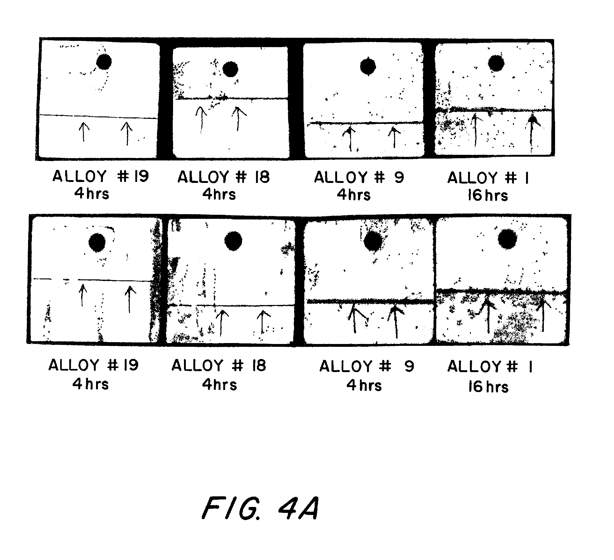
"The present invention provides an Al—Zn—Mg—Cu alloy for shaped castings that have ultimate tensile strengths greater than those of comparable castings of A356, while maintaining good resistance to stress corrosion cracking in severely corrosive environments of high tensile stress. The alloy has a unique combination of elements that optimize its performance, including a limited amount of Mg and Zn content and a high amount of Cu content. The alloy exhibits pitting corrosion, which is the preferred corrosion mode, and has acceptable hot cracking performance and fluidity for casting shaped products. The method of manufacturing a shaped casting involves preparing a molten mass of the alloy, casting it into a cast body, and heat treating it to an overaged condition. The resulting shaped casting has high stress corrosion cracking resistance and high tensile strength."

Problems solved by technology

Forged products are disadvantageously more expensive than cast products.
However these exhibit problems in castability, corrosion performance or fluidity, which are not readily overcome.
While the Al—Zn—Mg—Cu alloy disclosed in U.S. patent application Ser. No. 11 / 111,212 provides good general corrosion resistance, it has been determined that the alloy exhibits a less than optimum stress corrosion cracking (SCC) resistance in environments of high tensile stress and corrosion, which could limit it's application.

Method used


Image

  • HIGH STRENGTH, HIGH STRESS CORROSION CRACKING RESISTANT AND CASTABLE Al-Zn-Mg-Cu-Zr ALLOY FOR SHAPE CAST PRODUCTS
  • HIGH STRENGTH, HIGH STRESS CORROSION CRACKING RESISTANT AND CASTABLE Al-Zn-Mg-Cu-Zr ALLOY FOR SHAPE CAST PRODUCTS
  • HIGH STRENGTH, HIGH STRESS CORROSION CRACKING RESISTANT AND CASTABLE Al-Zn-Mg-Cu-Zr ALLOY FOR SHAPE CAST PRODUCTS

Examples


Embodiment Construction

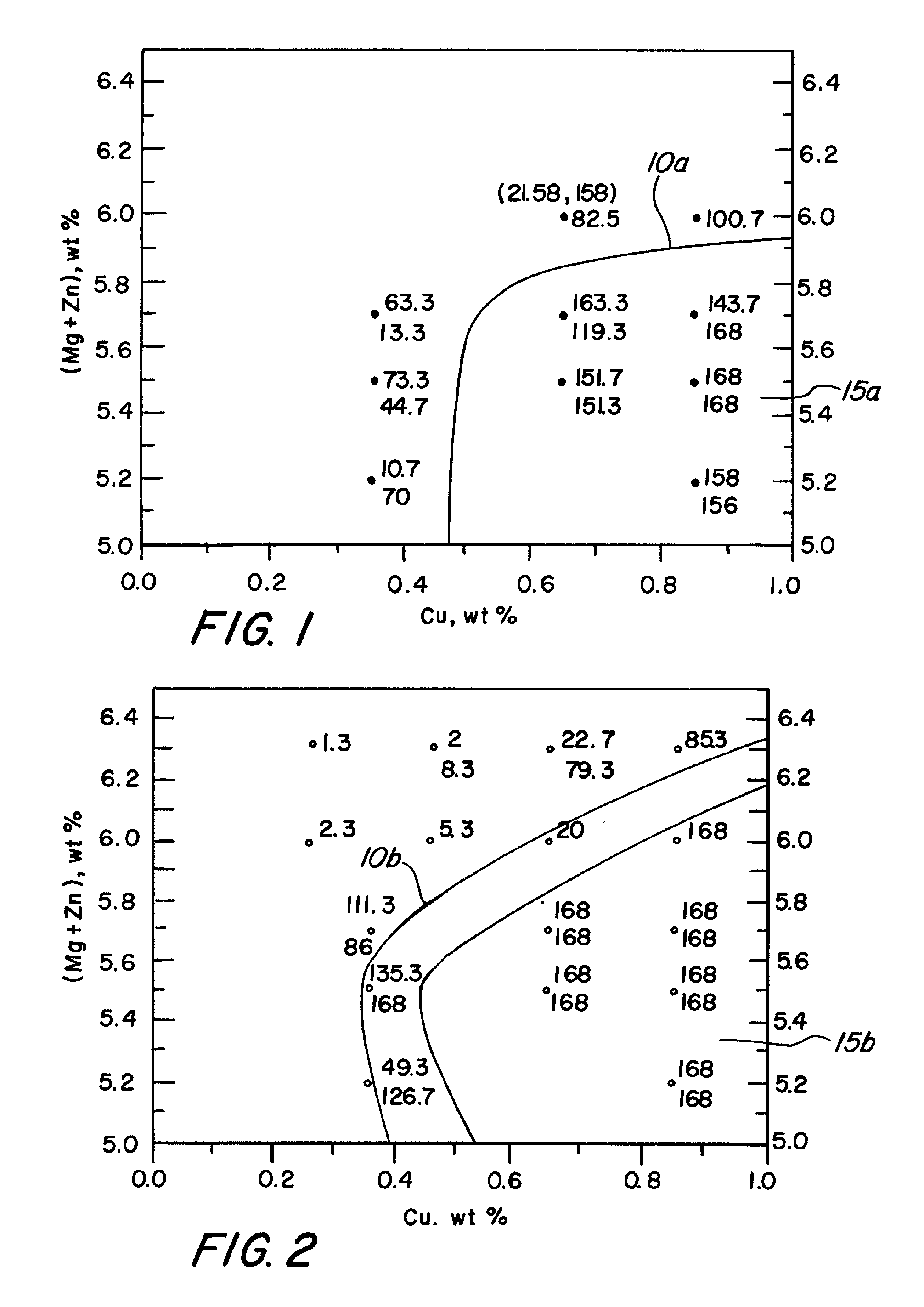
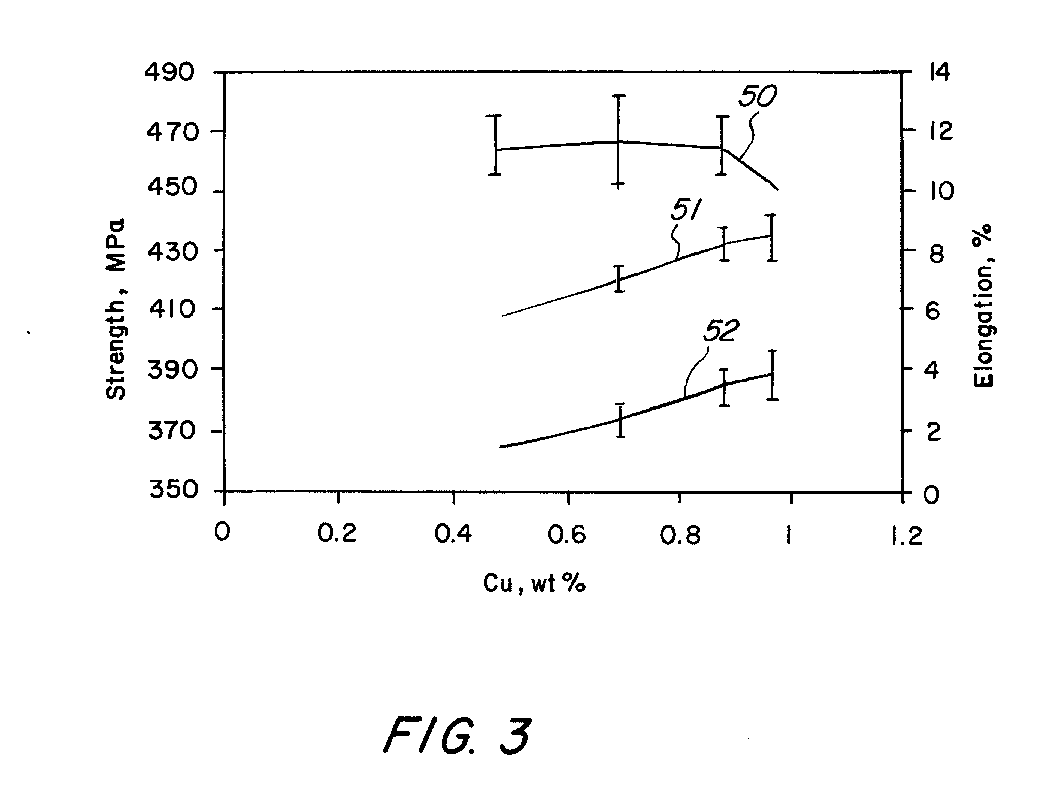
[0039]The present invention provides an Al—Zn—Mg—Cu alloy having yield strengths, fatigue strength, general corrosion performance, and stress corrosion cracking (SCC) performance suitable for automotive and aerospace applications. while maintaining castability. All component percentages herein are by weight percent unless otherwise indicated. When referring to any numerical range of values, such ranges are understood to include each and every number and / or fraction between the stated range minimum and maximum. A range of about 0.5-1.2 wt. % Cu, for example, would expressly include all intermediate values of about 0.6, 0.7, 0.8 and all the way up to and including 1.1 wt. % Cu. As used herein, the term “incidental impurities” refers to elements that are not purposeful additions to the alloy, but that due to impurities and / or leaching from contact with manufacturing equipment. trace quantities of such elements being no greater than 0.05 wt. % that may, nevertheless, find their way into...


PUM

PropertyMeasurementUnit
time-to-failureaaaaaaaaaa
temperatureaaaaaaaaaa

Abstract

The present invention provides an Al—Zn—Mg—Cu casting alloy that provides high strength for automotive and aerospace applications and optimized stress corrosion cracking resistance in highly corrosive and tensile environments. The inventive alloy composition includes about 3.5 wt. % to about 5.5 wt. % Zn; about 1.0 wt. % to about 3.0 wt. % Mg; about 0.5 wt. % to about 1.2 wt. % Cu; less than about 1.0 wt. % Si; less than about 0.30 wt. % Mn; less than about 0.30 wt. % Fe; and a balance of Al and incidental impurities.

Description

CROSS REFERENCE TO RELATED APPLICATIONS[0001]This application is a continuation of U.S. application Ser. No. 11 / 856,131, filed Sep. 17, 2007, which claims the benefit of U.S. Provisional Application No. 60 / 826,131, filed Sep. 19, 2006, each application of which is hereby incorporated herein by reference in its entirety.FIELD OF THE INVENTION[0002]This invention relates generally to aluminum alloys for aerospace and automotive shaped castings having high tensile strength and high resistance to stress corrosion cracking (SCC).BACKGROUND OF THE INVENTION[0003]Cast aluminum parts are used in structural applications in automobile suspensions to reduce weight. The most commonly used group of alloys, Al7SiMg, has well established strength limits. In order to obtain lighter weight parts, higher strength material is needed with established material properties for design. At present, cast materials made of A356.0, the most commonly used Al7SiMg alloy, can reliably guarantee ultimate tensile s...

Claims


Application Information

Patent Timeline
Patent Type & Authority Applications(United States)
IPC IPC(8): C22F1/053C22C21/16
CPCC22C21/10C22C1/06C22F1/053
Inventor LIN, JEN C.YAN, XINYANZHANG, WENPINGMORAN, JAMES P.NEWMAN, JOHN M.SAWTELL, RALPH R.SCOTT, GERALD D.BRANDT, MICHAELFORS, BOB R.BORNS, RICK A.MBAYE, MOUSTAPHA
Owner LIN JEN C
Learn More