
Extended life prosthetic hip joint

a prosthetic hip joint and life extension technology, applied in the field of prosthetic hip joints, can solve the problems of failure to wear, wear, and unknown cost of war injuries, and achieve the effect of improving surface roughness and sphericity

Inactive Publication Date: 2012-08-09
THOMPSON DANIEL C
View PDF5 Cites 4 Cited by
  • Summary
  • Abstract
  • Description
  • Claims
  • Application Information

AI Technical Summary

Benefits of technology

[0025]In order to maximize L, the fluid film parameter as defined above, and ensure full fluid film lubrication to minimize contact between the femoral head and acetabular cup and therefore wear, the following conditions are achieved: The femoral head diameter is as great as possible, or approximately the diameter of an “organic” femoral head. The preferred embodiment of the present invention includes a 40 mm diameter, but the diameter may range between 20 and 50 mm to approximate different sized organic femoral heads. This is as opposed to current practice, which is typically 20 to 25 mm. The diametric clearance, which is the difference between the femoral head diameter and the acetabular cup diameter, is reduced, from the current practice of approximately 100 μm (minimum) to 50 μm or less, with a lower limit of approximately 20 μm. The sphericity tolerance of the individual components is maintained to within a fraction (10%) of the diametric clearance, or within 5 μm. The 10% fraction is preferred because at that level (1) the measurement of dimensional errors is a reasonably efficient process, and (2) establishing the impact of errors below this level on joint performance would likely be obscured by other performance parameters. Such sphericity tolerance is achievable with state-of-the art precision manufacturing equipment. The surface of one of the two wear surfaces, preferably the femoral head is engineered and modified in order to amplify the hydrodynamic effect. The preferred engineered modification is a plurality of concave dimples on the surface of the femoral head where the dimples have a depth approximately equal to the diametric clearance. Composite surface roughness, Rac, is significantly reduced.
[0027]The femoral head is preferably 40 mm, but may be between 20 and 50 mm, which approximates the range of diameters of organic femoral heads. It is a feature of the present invention to minimize or lower the composite surface roughness, Rac, which is a function of the femoral head surface roughness, Rab, and the acetabular cup surface roughness, Ras, specifically the square root of the sum of their squares. The preferred method of achieving this feature is to reduce the femoral head surface roughness. Rac is less than 20 nm, and preferably less than 14 nm. As discussed below, it is another feature of the present invention to include an engineered surface, preferably the femoral head surface, such as a surface including dimples. The reduced femoral head surface roughness applies to the spaces between the dimples. This is because the greatest interaction between the ball and socket occur here, and any contact / wear will occur here. It is important that the introduction of the dimples not cause perturbations of the wear surface (e.g., at their lip).
[0049]The recent evolution of deterministic polishing, combined with appropriate metrology, now enables advances in the execution of advanced, low-wear designs. The combination of small clearances, tight manufacturing tolerances, and the engineered surface enable a hydrodynamic film, whereby relative motion between the femoral head and acetabular cup generates pressure in the body's own synovial fluid, which keeps surfaces separated. The cost savings to the U.S. medical system in terms of hip revision surgeries that would not have to occur is in the billions of dollars a year. The savings in pain, suffering, and recuperation for the patients is immeasurable.
[0053]It is a further aspect of the present invention to provide a prosthetic hip joint with improved sphericity.
[0054]It is a further aspect of the present invention to provide a prosthetic hip joint with improved surface roughness.
[0055]It is a further aspect of the present invention to provide a prosthetic hip joint with an amplified hydrodynamic film for wear minimization.

Problems solved by technology

The as yet unknown cost of war injuries will add to these figures.
The principal cause of failure is wear, and the consequences of wear (e.g., loosening of the femoral stem caused by reactions between human tissue and wear particles).
The results have not been entirely satisfactory.
Contact between the metal surfaces creates ionic wear debris, which reacts with body tissue causing loosening of the femoral stem and tissue inflammation.
Thus, it is clearly predictable that a typical prosthetic joint will operate in the boundary lubrication regime—which necessarily means that wear will occur.

Method used


Image

  • Extended life prosthetic hip joint
  • Extended life prosthetic hip joint
  • Extended life prosthetic hip joint

Examples


Embodiment Construction

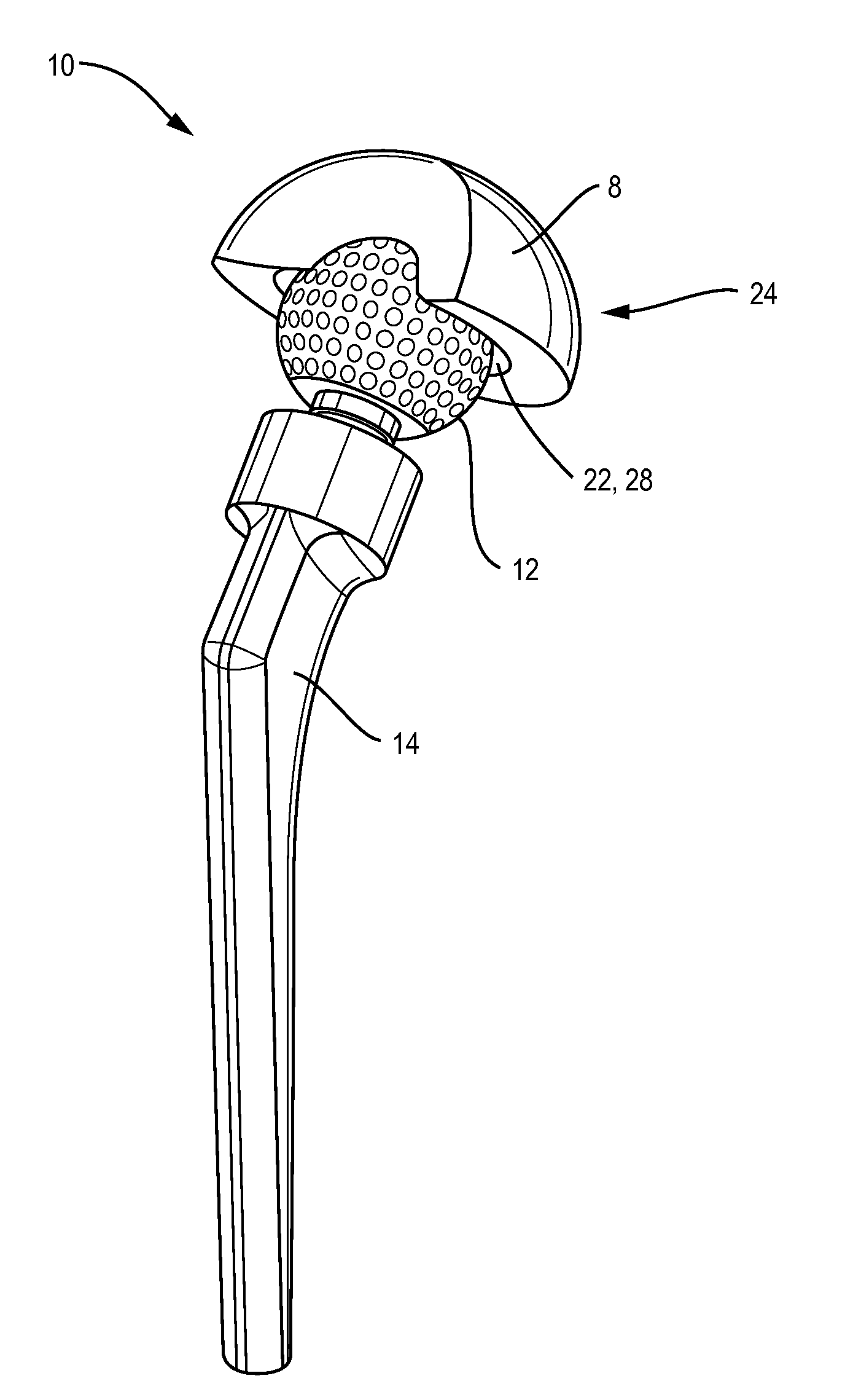
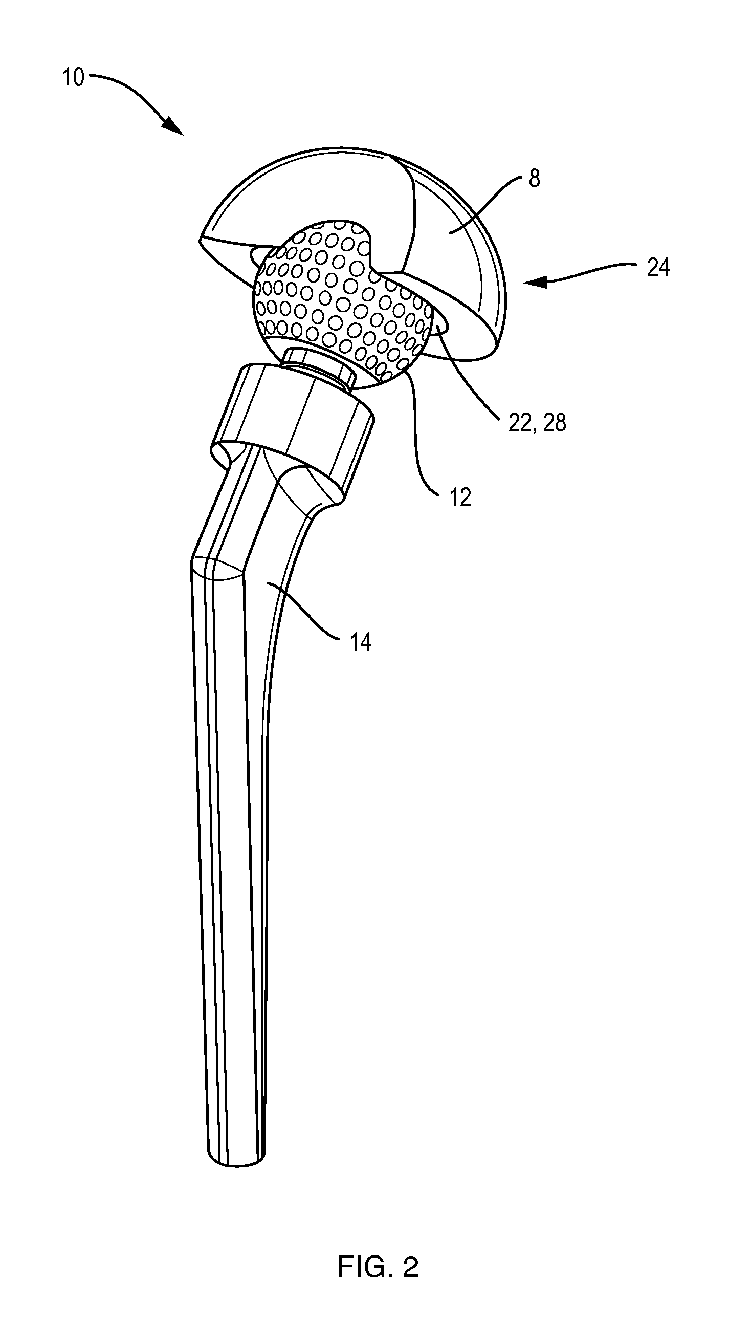
[0064]FIG. 2 is perspective view of prosthetic hip joint 10 of the present invention. In this view, we see acetabular cup 8 with acetabular cup surface 22, acetabular cup surface roughness 28, femoral head 12, femoral stem 14, and sphericity 24.

[0065]FIG. 3 is a partial cutaway of femoral head 12 and acetabular cup 8 of the present invention. Femoral head radius A is half of the femoral head diameter. Acetabular cup radius B is half of the acetabular cup diameter. Radial clearance H is the difference between A and B, and is half of the diametric clearance.

[0066]FIG. 4 is a perspective view of preferred femoral head 12 of the present invention, including dimples 18. Dimples 18 are engineered into femoral head surface 16 in a pattern similar to a golf ball. Dimples 18 have depth 20. Although not visible from this view, depth 20 is a measure of the indentation of dimple 18 into femoral head surface 16, away from the viewer. Depth 20 is preferably approximately equal to 2×H, or the diam...


PUM


Abstract

A prosthetic hard-on-hard orthopaedic hip joint comprising a femoral head with a diameter of approximately 40 mm and a dimpled surface, an acetabular cup with a diameter such that the diametric clearance is less than or equal to 50 μm, a sphericity less than 10% of the diametric clearance, a composite surface roughness less than 20 nm, and a femoral stem integral to said femoral head.

Description

FIELD OF THE INVENTION[0001]The present invention relates to prosthetic hip joints, and in particular, to hard-on-hard prosthetic hip joints with a hydrodynamic film.BACKGROUND[0002]In 2005 there were approximately 285,000 hip replacement surgeries in the U.S., at a total cost of approximately $11 B. Of these, approximately 41,000 (14.4%) were revisions, at a cost of approximately $2 B. With an aging, active population, the number of total hip replacements is expected to rise significantly and the cost of primary hip replacements in the U.S. is projected to grow to $23 B by 2030, with the associated cost of revisions growing to $3.9 B annually. The as yet unknown cost of war injuries will add to these figures.[0003]The average lifetime of a prosthetic hip joint is typically 10 to 15 years. The principal cause of failure is wear, and the consequences of wear (e.g., loosening of the femoral stem caused by reactions between human tissue and wear particles). More recently, because of se...

Claims


Application Information

Patent Timeline
IPC IPC(8): A61F2/32
CPCA61F2/32A61F2002/30673A61F2002/30937A61F2002/30934A61F2002/30787
Inventor THOMPSON, DANIEL C.
Owner THOMPSON DANIEL C
Learn More