
Toner and method for producing the same, toner container, developer, image forming apparatus and process cartridge

a technology of toner and development method, applied in the field of non-magnetic toner, can solve the problems of difficult to transfer all of the spherical toner particles degrade the heat-resistance/storage stability of the toner, and expose the release agent to the toner surface, etc., to achieve stable charge characteristics, developability and transferability, and high quality

Inactive Publication Date: 2008-09-25
RICOH KK
View PDF20 Cites 25 Cited by
  • Summary
  • Abstract
  • Description
  • Claims
  • Application Information

AI Technical Summary

Benefits of technology

The present invention provides a non-magnetic toner that has good chargeability and durability, and can be fixed at low temperatures. The toner is produced by a method that involves dispersing toner particles in an aqueous medium, heating the dispersion to a temperature where the releasing agent melts, and washing and drying the toner. The toner is compatible with low-temperature fixability and heat-resistance / storage stability. The invention also provides a developer, an image forming apparatus, and a process cartridge that use this new toner. The toner does not cause stains and has good chargeability.

Problems solved by technology

Additionally, in the case of the heat fixing methods, the heating temperature is preferably as low as possible for the purpose of energy saving; however, if the thermal properties of the binder resin included in the toner is designed to be compatible with too low temperatures in order to attain low-temperature fixability, the heat-resistance / storage stability of the toner is degraded, and there occur problems such as blocking.
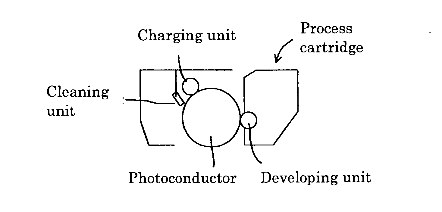
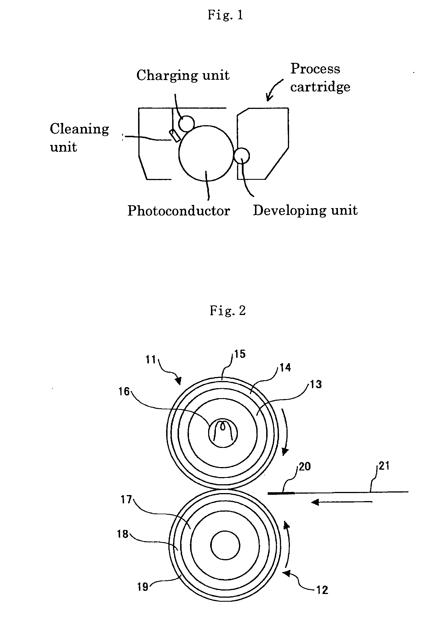
However, it is difficult to transfer all of such spherical toner particles, and toner particles remaining on the photoconductor and other members need to be removed.
However, the conventional blade cleaning method suffers from a disadvantage that spherical toners tend to slip through the blade to cause problems.
Additionally, when a toner containing a sufficient amount of releasing agent is produced by using the above-described solution suspension method, it is often the case that the releasing agent is exposed to the toner surface and, in some cases, stains the developing members.
The releasing agent can also be embedded deeply in the interior of the toner; however, when the releasing agent is too deeply embedded, bleeding of the releasing agent upon fixation becomes insufficient, leading to generation of offset.

Method used


Image

  • Toner and method for producing the same, toner container, developer, image forming apparatus and process cartridge
  • Toner and method for producing the same, toner container, developer, image forming apparatus and process cartridge

Examples


example 1

Preparation of Dispersion Liquid

Oil Phase

[0164]In a vessel equipped with a stirring rod and a thermometer, 96 parts of the [polyester 1], 32 parts of paraffin wax (melting point: 72° C.) and 383 parts of ethyl acetate were placed, and the reaction mixture thus obtained was increased in temperature under stirring to 80° C., maintained at 80° C. for 5 hours, and thereafter cooled down to 30° C. over a period of 1 hour. The mixture thus obtained was transferred to another vessel, and the mixture was dispersed by using a beads mill (Ultravisco mill, manufactured by Aimex Co., Ltd.) under the conditions that the liquid feeding rate was 1 kg / hr, the disk circumferential speed was 6 m / sec, 0.5-mm zirconia beads were loaded such that they make up 80% by volume of the interior or the mill, and the number of pass was three. In this way a [raw material dissolved liquid 1] was obtained. Then, 325 parts of the [raw material dissolved liquid 1] was added with 338 parts of a 70% by mass ethyl acet...

example 2

[0177]A [developer 2] of the present invention was obtained in the same manner as in Example 1 except that the fed amount of paraffin wax in the preparation of the dispersion liquid (oil phase) in Example 1 was changed to 5 parts.

[0178]The volume average particle size (Dv) and the number average particle size (Dn) of the obtained [toner base 2] were 5.4 μm and 4.9 μm, respectively, and Dv / Dn was 1.10 and the average circularity was 0.971. The peak intensity ratio R of the peak intensity derived from the Pes skeleton (bisphenol derivative) to the peak intensity derived from the releasing agent (ethylene chain), as measured ATR-IR method, was found to be 0.082.

[0179]The endothermic amounts H1 and H2 of the releasing agent included in the toner, measured by the DSC method, were found to be 6.6 (mJ / mg) and 6.4 (mJ / mg), respectively, to give a ratio of H2 / H1=0.97.

example 3

[0180]A [developer 3] of the present invention was obtained in the same manner as in Example 1 except that the releasing agent in Example 1 was replaced with paraffin wax (melting point: 68° C.). The heating temperature in the heat treatment was set at 76° C. so as to be higher by 8° C. than the melting point of the releasing agent.

[0181]The volume average particle size (Dv) and the number average particle size (Dn) of the obtained [toner base 3] were 5.7 μm and 5.1 μm, respectively, and Dv / Dn was 1.12 and the average circularity was 0.974. I The peak intensity ratio R of the peak intensity derived from the Pes skeleton (bisphenol derivative) to the peak intensity derived from the releasing agent (ethylene chain), as measured ATR-IR method, was found to be 0.038.

[0182]The endothermic amounts H1 and H2 of the releasing agent included in the toner, measured by the DSC method, were found to be 3.8 (mJ / mg) and 3.7 (mJ / mg), respectively, to give a ratio of H2 / H1=0.97.


PUM

PropertyMeasurementUnit
melting pointaaaaaaaaaa
molar ratioaaaaaaaaaa
particle sizeaaaaaaaaaa

Abstract

Disclosed is a non-magnetic toner for use in developing electrostatic toner image, wherein the toner is produced by a toner production method that includes: dispersing in an aqueous medium an organic dispersion liquid that comprises in an organic solvent a pigment, a binder resin and / or a binder resin precursor, and a releasing agent; removing the organic solvent to prepare a dispersion slurry in which toner particles are dispersed in the aqueous medium; heating the dispersion slurry to a temperature equal to or higher than the melting point of the releasing agent; and washing the toner particles.

Description

BACKGROUND OF THE INVENTION[0001]1. Field of the Invention[0002]The present invention relates to a non-magnetic toner for use in developing electrostatic images, a developer using the toner, a toner container and an image forming apparatus.[0003]2. Description of the Related Art[0004]As a method for fixing toner, a contact heat fixing method such as a heat roller fixing method has hitherto been widely adopted. A fixing apparatus used in the heat roller fixing method is equipped with a heat roller and a pressure roller, and by making a recording sheet carrying a toner image pass through a pressure contact section (nip section) between the heat roller and the pressure roller, the fixing apparatus melts the toner image to be fixed on the recording sheet.[0005]In the contact heat fixing method typified by the heat roller fixing method, fixing is carried out by bringing the surface of a heating member (for example, a heat roller) of a contact heat fixing apparatus into contact with a ton...

Claims


Application Information

Patent Timeline
Patent Type & Authority Applications(United States)
IPC IPC(8): G03G9/087G03G15/06
CPCG03G9/0804G03G9/0806G03G9/08784G03G9/08764G03G9/08782G03G9/08755
Inventor NOZAKI, TSUYOSHINOZAKI, CHIYOSHIYAMAMOTO, ATSUSHIMATSUMOTO, MITSUYOKADOTA, TAKUYAKUROSE, KATSUNORIISHIKAWA, YOSHIMICHI
Owner RICOH KK
Learn More