
Method of manufacturing collated t-nuts

a technology of collated t-nuts and collated t-nuts, which is applied in the field of collated t-nuts, can solve the problems of affecting the adhesive properties of tape, t-nuts can easily become detached or ‘unstuck’ from tape, and the taped t-nuts on the coil do not withstand impact well, so as to facilitate the installation process of the fastener

Inactive Publication Date: 2012-07-19
STAFAST PROD
View PDF5 Cites 11 Cited by
  • Summary
  • Abstract
  • Description
  • Claims
  • Application Information

AI Technical Summary

Benefits of technology

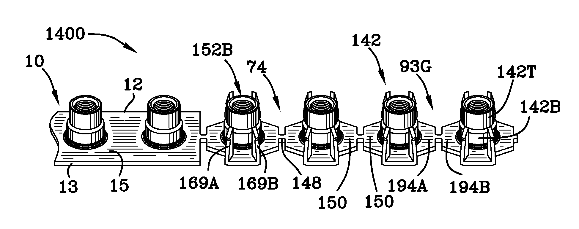
[0012]Barrels can have the option of having skives on them. Skives cause the T-Nut to twist upon insertion and help increase retention of the T-Nut in the component. This type of T-Nut is known as a Propell nut. The Propell T-Nut has various flange sizes and geometries. The flanges may have various features such as prongs, holes, and welding bosses of any size and configuration. Carry tabs are used to connect each T-Nut to another. Carry tabs are either frangible themselves or include a frangible portion. Size, shape and location of the carry tabs can vary. All T-nut configurations disclosed herein may have various flange sizes and geometries.
[0016]Steel or stainless steel coil T-Nuts have advantages over individual detached T-Nuts. Complete manufacturing is executed in one single operation or series of operations. T-Nuts are formed, tapped, and rolled up on a coil without requiring any secondary operations. The time to produce T-Nuts decreases and production costs are reduced. Because T-Nuts are collated on a coil they can be wound up on a reel instead of being packaged in cardboard boxes, which reduces packaging costs. Some T-Nuts have geometries that typically present feeding issues in vibratory bowls and tracks. Collated T-Nuts of the invention simplify the feeding process by eliminating the need for a vibratory bowl and track. T-Nut machines that feed T-Nuts using a vibratory bowl and track can experience feeding issues in a dusty / dirty environment.
[0017]T-Nut users in woodworking related industries experience problems with sawdust. Sawdust in the atmosphere can settle on the T-Nuts and cause jamming in vibratory bowls and tracks. Collated T-Nuts on a steel or stainless steel coil do not require vibratory bowls and tracks, therefore eliminating potential jamming. The collated parts disclosed herein that are fed into automation equipment do not require an electrical vibratory system to feed parts. Steel or stainless steel coil T-Nuts can be easily fed into automation equipment.
[0018]The need for lifting boxes of individual T-Nuts and pouring them into a vibratory machine hopper is eliminated by the invention. Multiple steel or stainless steel coils of the T-Nuts rolled up into a coil as disclosed herein can be stored directly on the machine frame and easily reloaded as needed. Also, since the T-Nut coils disclosed herein are stable, a larger coil can be loaded onto a pallet reel and fed into an installation machine to run even larger quantities of T-Nuts before having to reload.
[0031]It is an object of the invention to provide a coiled roll of T-Nuts which is stable and secure for feeding the T-Nuts into a machine which severs the T-Nuts and places them securely in a substrate.
[0038]It is an object of the invention to form T-Nuts on and of a metal strip such that the T-Nuts may be reliably separated and installed in a wooden substrate.

Problems solved by technology

First, T-Nuts can easily become detached or ‘unstuck’ from the tape.
Factors such as temperature and humidity can have an adverse reaction on the adhesive properties of tape.
Second, taped T-Nuts on a coil do not withstand impact well.
Common forces involved with activities such as shipping and / or handling can cause T-Nuts to detach.
Third, the tape is flexible and the coil of T-Nuts does not have very rigid structure.
If they are moved into a vertical angle they can lose their coiled form and begin to unravel.

Method used


Image

  • Method of manufacturing collated t-nuts
  • Method of manufacturing collated t-nuts
  • Method of manufacturing collated t-nuts

Examples


Embodiment Construction

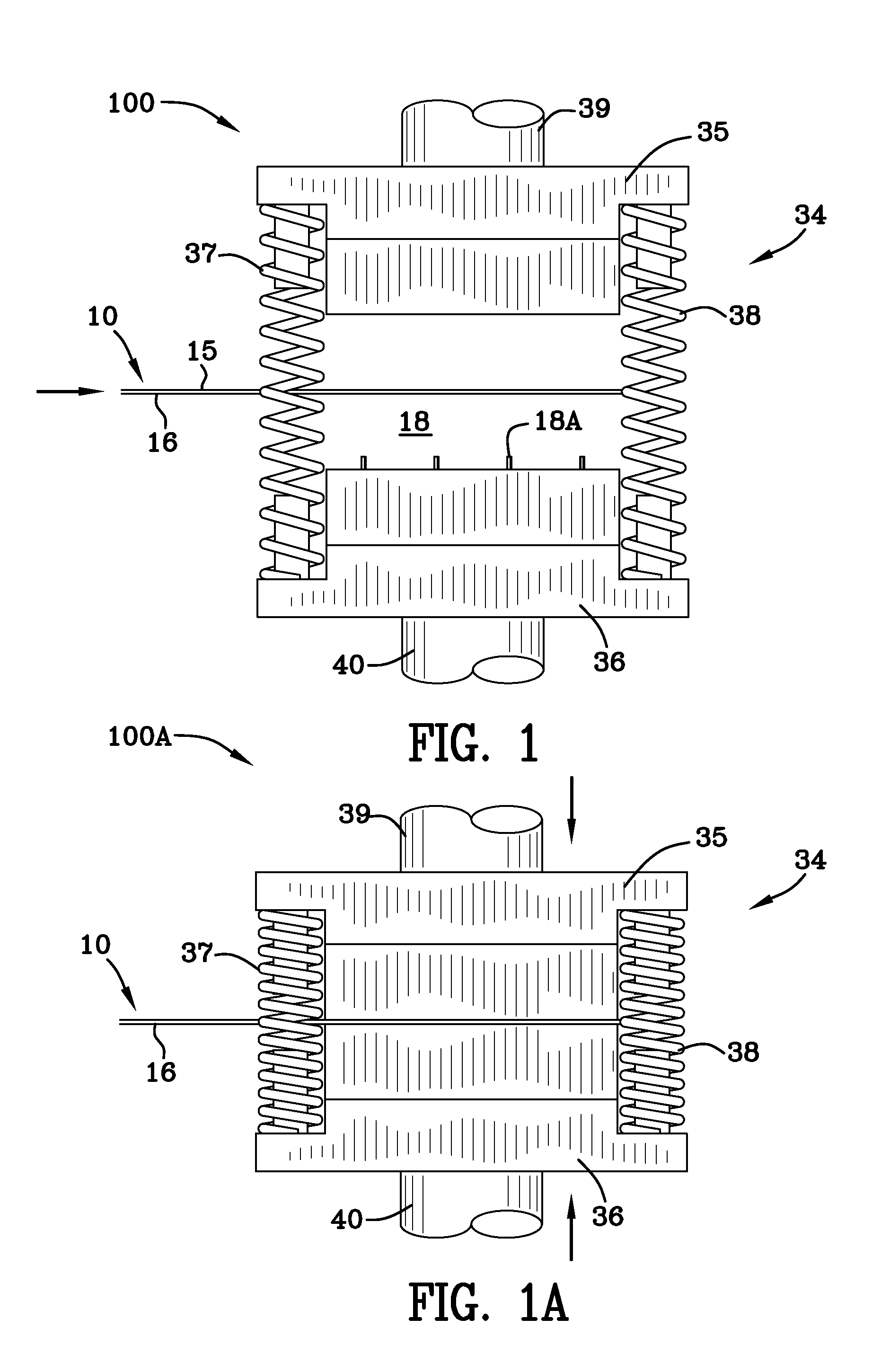
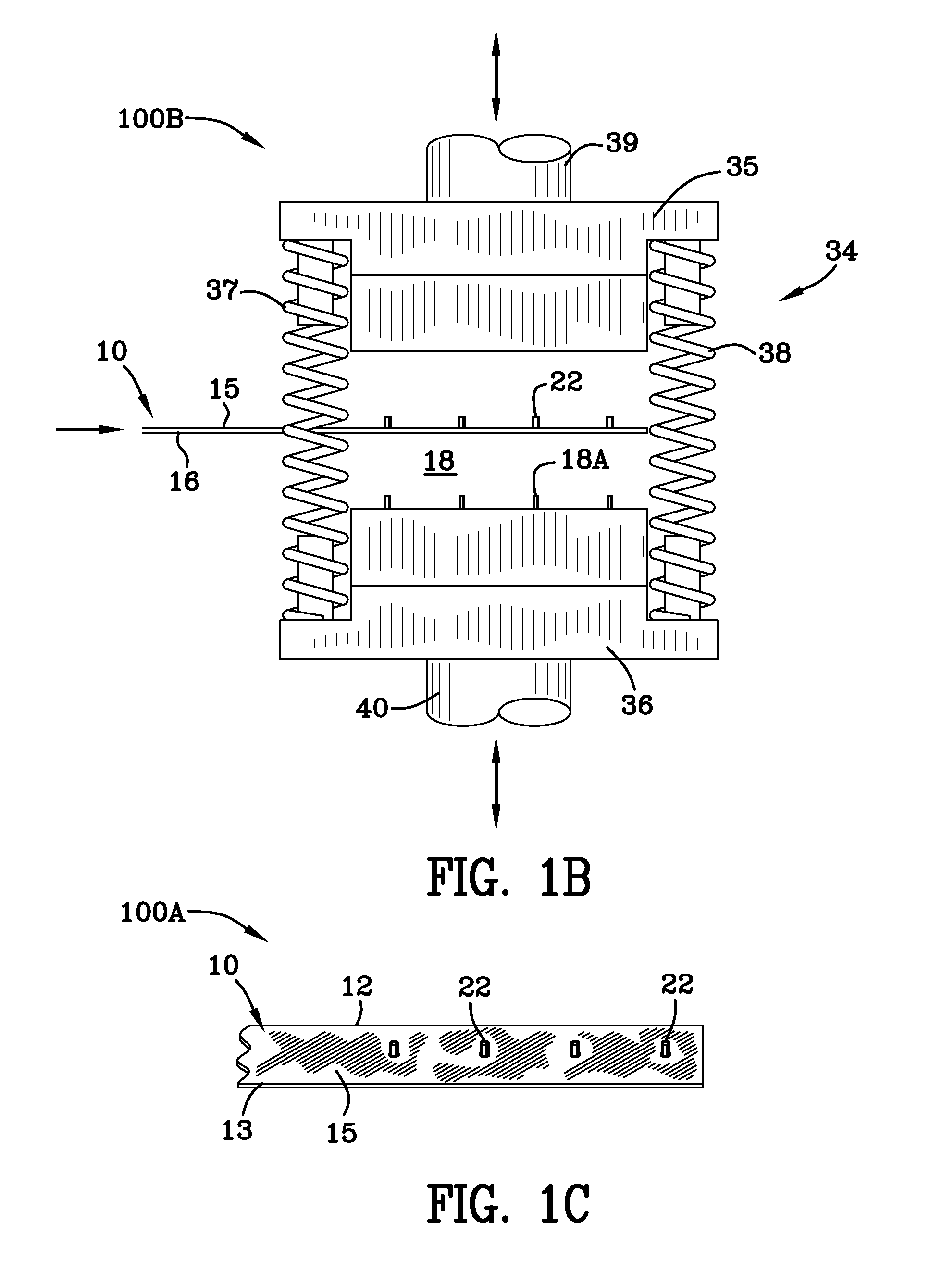
[0120]Reference may be had to FIG. 4 for a quick understanding of the continuous strip of collated T-Nuts of the invention. The continuous strip comprises T-Nuts integrally connected together and spaced apart for later dispensation in a substrate. The integrally connected T-Nuts are formed on and from a continuous steel strip 10. The strip shown in FIG. 4 has been identified by the reference numeral 33. Put another way, reference numeral 33 identifies one example of the completed product, namely, a strip of collated T-Nuts with flanges and parts linked together by carry tabs and frangible portions. As stated previously, the carry tabs may be frangible or portions of the carry tabs may be frangible. The strip of deformable metal material 10 (FIG. 1) has first and second side portions 12, 13 and top and bottom portions 15, 16 and is fed into a first die station 18 (FIGS. 1, 1A, 1B) which is housed in press 34. FIGS. 1, 1A and 1B illustrate a die press at a first die station 18 in thre...


PUM

PropertyMeasurementUnit
thicknessesaaaaaaaaaa
widthsaaaaaaaaaa

Abstract

A continuous strip of T-Nuts formed on a common strip of metal. Each T-Nut of the strip of T-Nuts is integrally connected to the next adjacent T-Nut by carry tabs. The carry tabs can be frangible themselves or contain a frangible portion. Each T-Nut includes a cylindrical bore therein and a threaded interior. A mechanism feeds and severs the endmost T-Nut in endwise fashion. The mechanism to feed and sever the endmost T-Nut includes a cutting blade positioned vertically below the frangible portion of the carry tab. A shearing ram having a guide positioned axially in line with the cylindrical bore in the endmost T-Nut is adapted to move vertically from an upper to a lower position to engage the cutting blade with the frangible portion and sever the endmost T-Nut.

Description

[0001]This application claims priority to and the benefit of copending United States Provisional Patent Application Ser. No. 61 / 433,300 filed Jan. 17, 2011. United States Provisional Patent Application Ser. No. 61 / 433,300 filed Jan. 17, 2011 is incorporated in its entirety by reference hereto.FIELD OF INVENTION[0002]The invention is in the field of fasteners.BACKGROUND OF THE INVENTION[0003]Existing collated fasteners are manufactured and then collated using a secondary process. One process uses a progressive die method to cut the T-Nuts off from the steel or stainless steel strip and then tap the threads in a secondary process. The secondary process commonly uses glue to hold the fasteners together for later dispensation. Fasteners which are glued together include staples, nails, screws, clips, etc.[0004]One known method for collating T-Nuts includes adhering the T-Nuts to tape and rolling them into a coil during a secondary operation. FIG. 13 is a view 1300 illustrating a prior ar...

Claims


Application Information

Patent Timeline
Patent Type & Authority Applications(United States)
IPC IPC(8): B21K1/66B23P13/00
CPCB23D33/02B23P19/001B23P19/062F16B27/00F16B37/02F16B37/04Y10T29/49799Y10T29/5198Y10T83/647B23D33/025B21K1/64Y10T29/49947
Inventor DIETER, JONATHAN WAYNESELLE, STEPHEN R.
Owner STAFAST PROD
Learn More