
Lighting

a technology of light and light source, applied in the field of improvement, can solve the problems of reducing affecting the service life of the electrical wiring connection, and affecting the service life of the system, so as to reduce the effect of usage, reduce the potential for departure delays, and shorten the period of time

Active Publication Date: 2012-07-12
SAF T GLO
View PDF2 Cites 9 Cited by
  • Summary
  • Abstract
  • Description
  • Claims
  • Application Information

AI Technical Summary

Benefits of technology

"The invention provides emergency lighting for aircraft or buildings using electric double-layer capacitors as the power source, instead of batteries. This solves the problem of battery life and allows for more reliable and consistent operation of the emergency lighting. The electric double-layer capacitors can be quickly charged when the aircraft power supply is available, and the system can still operate even if the aircraft power supply fails. The light sources can be LEDs, which are reliable, efficient, and can be retrofitted into existing light units. The use of LEDs and electric double-layer capacitors reduces the size and weight of the emergency lighting system."

Problems solved by technology

Such systems may be rendered inoperable following an accident if the electrical wiring connections to the power source are damaged.
For example, the electrical wiring connections may be broken by impact damage to the structure of the aircraft, and / or by fire and / or by water if the aircraft has to make an emergency landing on land or in the sea.
Maintaining electric-double layer capacitors with a high voltage level may reduce their service life.
This may prolong the life of the capacitors in service.
Furthermore repeated testing on a regular basis will have little or no impact on the useful service life of the back-up power supply as the test does not fully discharge the back-up power supply.
The amount of energy consumed in this measurement may be small and the time short, leaving the capacitor adequately charged with a known quantity of stored energy.
If a fault is detected at this stage that requires a repair, this may result in the aircraft being delayed and missing a take-off slot.
Also, faults that may develop in the system after such testing are only detected the following day when the system is next tested.

Method used


Image

  • Lighting
  • Lighting

Examples


Embodiment Construction

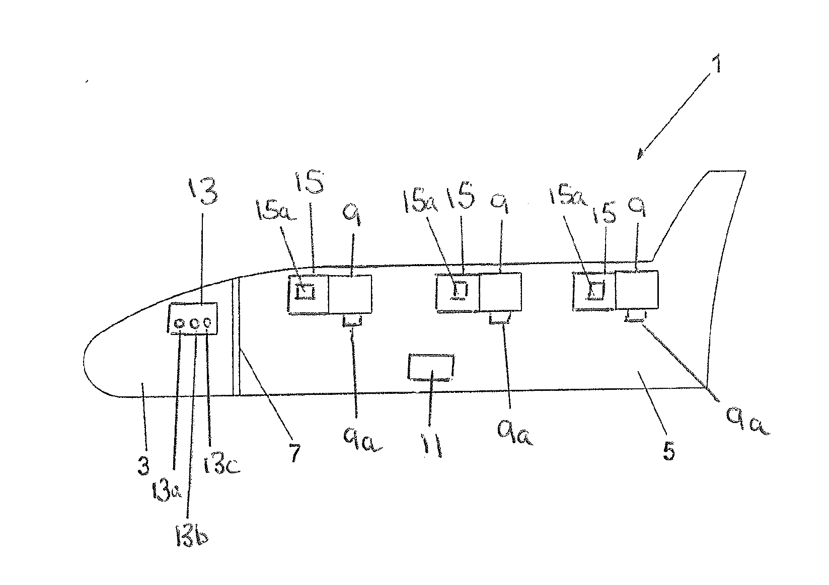
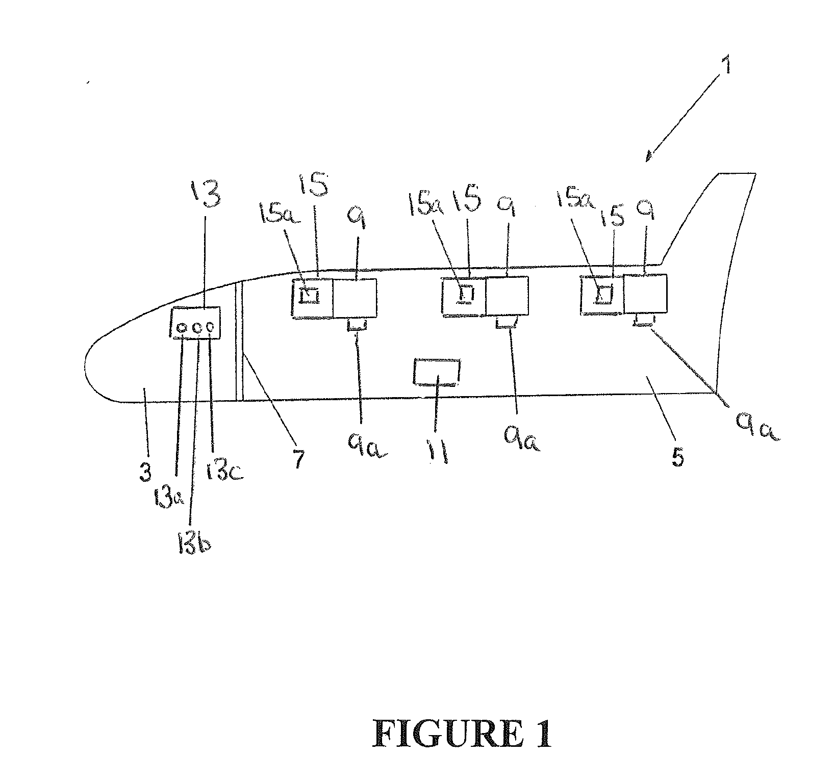
[0051]Referring to the drawing, an aircraft 1 has a flight deck 3 separated from the passenger cabin 5 by a bulkhead 7 having a door (not shown) for access to the flight deck 3 from the passenger cabin 5. FIG. 1 shows the aircraft with parts not relevant to understanding the invention omitted for clarity.

[0052]The aircraft 1 is provided with an emergency lighting system for directing passengers and crew to exits (not shown) when the normal aircraft lighting is not working for any reason, for example in an emergency following a crash, and the aircraft has to be evacuated in a short period of time.

[0053]The emergency lighting includes a plurality of light units generally indicated by reference numeral 9. Three light units 9 are shown but it will be understood that any number of light units 9 may be employed to suit the requirements for a given layout of the passenger cabin 5 and exits. The light units 9 may be provided at any suitable location within the passenger cabin 5, for example...


PUM


Abstract

Emergency lighting for an aircraft has a primary power source for light units provided by the normal aircraft power supply and a secondary power source provided by power supply units operable to back-up the primary power source. Each light unit may have its own power supply unit operable to power the light unit in an emergency if the normal aircraft power supply fails or is otherwise unable to power the emergency lighting. Each power supply unit includes one or more electric double layer capacitors that are charged whenever the normal aircraft power supply is operational to provide the primary power source. The useful life of the electric double layer capacitors may be prolonged by reducing the capacitor voltage when the emergency lighting is switched off.

Description

FIELD OF THE INVENTION[0001]This invention concerns improvements in or relating to lighting and in particular, but not exclusively, emergency lighting for a passenger transport vehicle such as an aircraft, train, ship and the like so as to guide passengers to an exit when the vehicle is evacuated. The invention further relates to power sources for such units and more especially to a method of monitoring or checking the condition of the power source to provide an indication when the power source may need to be replaced / recharged. The invention has application to emergency lighting both for fitting to new vehicles and for retrofitting to existing vehicles. For convenience, the invention is described hereinafter for use in aircraft but it will be understood the invention has application to other passenger vehicles and in at least some aspects may have application to buildings, especially in a wayfinding system to assist evacuation in an emergency.BACKGROUND OF THE INVENTION[0002]Conven...

Claims


Application Information

Patent Timeline
Patent Type & Authority Applications(United States)
IPC IPC(8): B64D47/02
CPCB64D11/00B64D47/02H02J9/065B64D2045/007B64D2203/00B64D2011/0038H02J2310/40H02J2310/44B60Q3/46B64D25/00H02J9/06
Inventor RUST, DANIEL ALAN
Owner SAF T GLO
Learn More