
System architecture for virtual rendering of a print production piece

a technology of system architecture and print production, applied in the field of preprint virtual rendering and depiction of print jobs, can solve the problems that the technology of producing virtual renderings of finished print pieces is generally limited to providing only a two-dimensional perspective, so as to improve efficiency, reduce production costs, and improve business. the effect of condu

Inactive Publication Date: 2012-06-28
XEROX CORP
View PDF6 Cites 18 Cited by
  • Summary
  • Abstract
  • Description
  • Claims
  • Application Information

AI Technical Summary

Benefits of technology

[0104]One difficulty with systems which support a 3D virtual rendering of a finished document is the multitude of different binding types (e.g. coil, comb-wire, comb-plastic, ring, clip, staples, etc) which come in different sizes (length & diameter), pitch, color, etc. The 3D rendering system may need access to several thousand different 3D models depending upon the specifics of a particular shop configuration. Aspects of the system and methods described herein provide for the efficient storage and subsequent presentation of realistic 3D models for a number of binding types with a large assortment of customization attributes.
[0229]Color—the RGB values of the staple, where this is typically black or grey, but a contrasting color may be used to increase visibility for testing;

Problems solved by technology

The existing technologies that produce virtual renderings of a finished print piece are generally limited to providing only a two dimensional perspective.
There are a few applications that provide a 3D rendering, but they are commonly implemented as a vector graphics-based animation application with full-screen navigation interfaces, graphic illustrations, and simple interactivity in an antialiased, resizable file format that is small enough to stream across a normal modem connection (e.g., FLASH™) or high-level computer programming languages that allow small application programs to be downloaded from a server to a client along with data that each program processes (e.g., JAVA™) and may require users to install undesirable plug-ins or run special applications.

Method used


Image

  • System architecture for virtual rendering of a print production piece
  • System architecture for virtual rendering of a print production piece
  • System architecture for virtual rendering of a print production piece

Examples


Embodiment Construction

1.0 System and Architecture

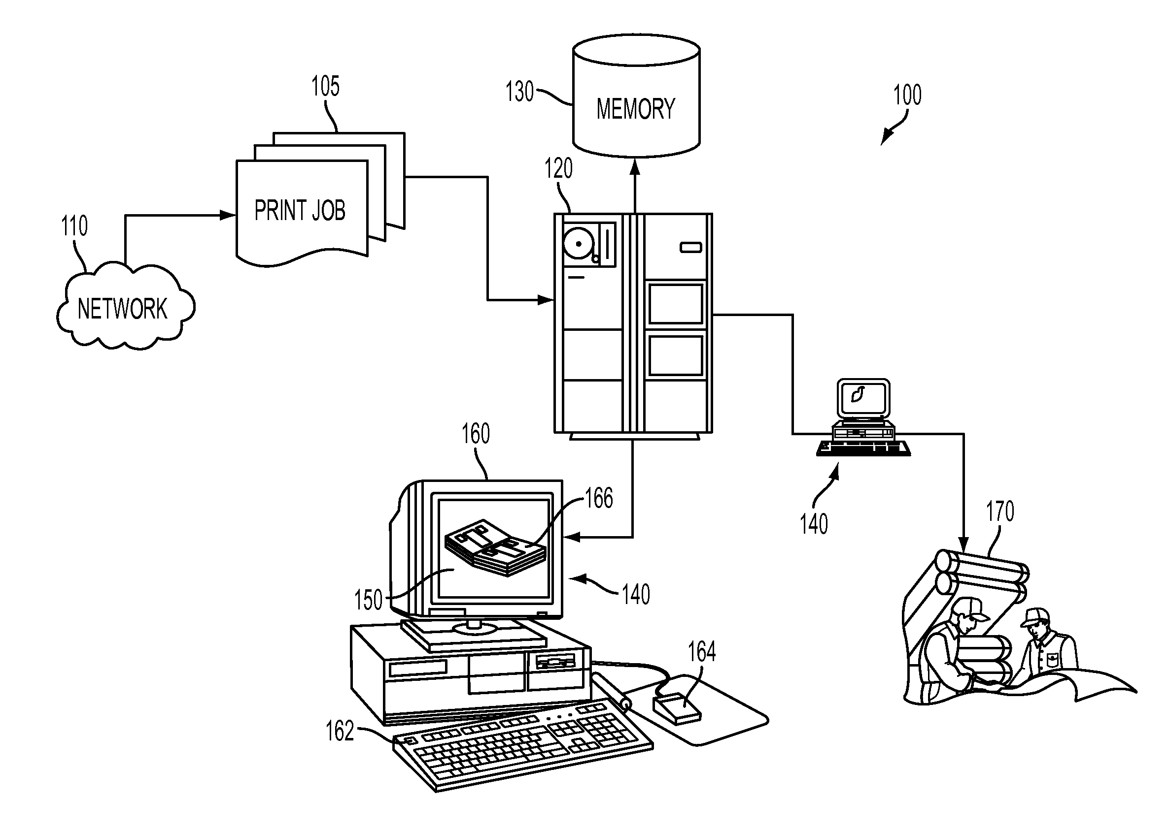
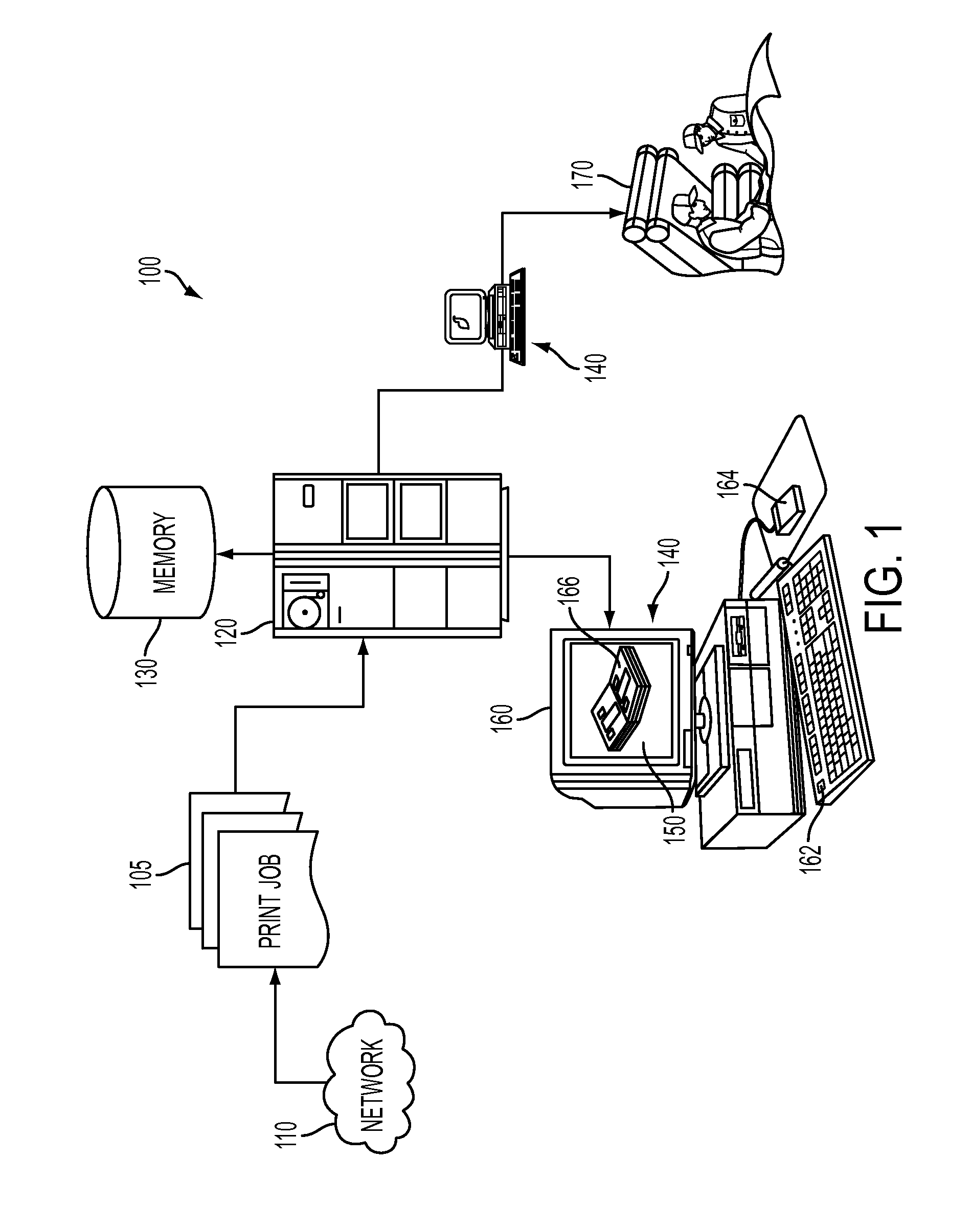
[0070]In FIG. 1 there is depicted an exemplary system 100 upon which the following disclosure and methodology may be implemented. It is to be understood that certain aspects of the system would operate in accordance with pre-programmed instructions stored on various media and used to operate a local or networked computer system to carry out such features, and perhaps across a plurality of interconnected computers at a time. Such a system might include a commercially available personal computer with appropriate graphics rendering capability, that can also be associated with a computer storage medium (e.g., removable disk or similar portable media, RAM, ROM, and other non-transitory means for storing digital information that may be at least read by a computer) or similar memory devices and where the system is accessible, perhaps via an Internet or intranet for submission of print jobs. It is also contemplated that one or more aspects of the system may be imp...


PUM


Abstract

A system and method for a pre-print, three-dimensional virtual rendering of a print piece is disclosed. A plurality of modular / pipelined architectural layers are managed, operated, and organized by a controller. A product definition is provided to a job ticket adaptation layer where it is transformed into a physical model. The physical model is then transformed into a display model via the product model layer. The display model is transformed into a scene that can be displayed on a graphical user interface as a three dimensional virtual rendering by a rendering layer, where the binding elements may further include 3D binding models as well as 2D textures on 3D surfaces to simulate 3D models.

Description

CROSS-REFERENCE TO RELATED APPLICATIONS[0001]Priority is claimed from U.S. Provisional Patent Application No. 61 / 427,364 by Rolleston et al., filed Dec. 27, 2010 for “SYSTEM ARCHITECTURE FOR VIRTUAL RENDERING OF A PRINT PRODUCTION PIECE,” and cross reference is made to the following application, U.S. Patent Application Publication No. 2006 / 0114490, U.S. Ser. No. 11 / 001,431, entitled “SYSTEM AND METHOD FOR DOCUMENT PRODUCTION VISUALIZATION,” filed Dec. 1, 2004 by Robert J. Rolleston, both of which are hereby incorporated by reference in their entirety for their teachings. Cross reference is also made to the following concurrently-filed applications that are each hereby incorporated by reference in their entirety:[0002]a) Atty Docket No. 20090600-US-NP, for a SYSTEM AND METHOD EMPLOYING 3D MODELS IN VIRTUAL RENDERING OF A PRINT PRODUCTION PIECE, by R. Rolleston et al. filed concurrently herewith;[0003]b) Atty Docket No. 20091255-US-NP, for a SYSTEM AND METHOD EMPLOYING SEGMENTED MODEL...

Claims


Application Information

Patent Timeline
Patent Type & Authority Applications(United States)
IPC IPC(8): G06T15/00
CPCG06F3/1208G06F3/1285G06F3/1256G06T15/00
Inventor ROLLESTON, ROBERT J.COTE, ALAN T.SEMBOWER, NEIL R.HARRINGTON, STEVEN J.VALOBRA, PASCAL
Owner XEROX CORP
Learn More