
Microfluidic-channel embeddable, laterally oscillating gravimetric sensor device fabricated with micro-electro-mechanical systems (MEMS) technology

a gravimetric sensor and microfluidic channel technology, applied in the field of laterally oscillating gravimetric sensing device embeddable, can solve the problems of preventing high resolution and on-line monitoring, low quality oscillation, and significant reduction of the mass of the cantilever, and achieves the effect of easy production

Active Publication Date: 2012-06-14
MIKROBIYOSISTEMLER ELECTRONICS SAN & TIC AS
View PDF3 Cites 5 Cited by
  • Summary
  • Abstract
  • Description
  • Claims
  • Application Information

AI Technical Summary

Benefits of technology

[0024]Since the oscillation is lateral, the quality factor within the liquid is quite high. Thus, it is possible to have online and high resolution detection.
[0036]Since it does not require optical systems, fixed costs required for the operation of this device are further decreased.

Problems solved by technology

Main drawbacks of cantilever type gravimetric detectors are as follows: 1) Vertical oscillation nature with respect to the large area of the cantilever results in squeeze film damping to be more dominant, and thus leads to a very low quality oscillation (quality factor is a parameter indicating the bandwidth of the oscillation; narrower the bandwidth is, higher the frequency resolution and quality factor is) or prevents the oscillation due to over damping within the liquid.
Therefore, cantilever method prevents high resolution and on-line monitoring.
2) In order to overcome explained low quality factor problem, mass of the cantilevers is decreased significantly and hence the operating frequency is increased too much.
Since electronic methods are insufficient in such large frequencies, expensive optical excitation and read-out methods are needed.
This situation usually decreases the quantitative concentration resolution.

Method used


Image

  • Microfluidic-channel embeddable, laterally oscillating gravimetric sensor device fabricated with micro-electro-mechanical systems (MEMS) technology
  • Microfluidic-channel embeddable, laterally oscillating gravimetric sensor device fabricated with micro-electro-mechanical systems (MEMS) technology
  • Microfluidic-channel embeddable, laterally oscillating gravimetric sensor device fabricated with micro-electro-mechanical systems (MEMS) technology

Examples


Embodiment Construction

[0070]The device and the method developed through this invention are basically comprised of four (4) main groups as:

[0071]Resonator that is embeddable under microfluidic channel

[0072]Components of the bio-activation layer

[0073]Micro fluidic channel

[0074]Microfabrication technique

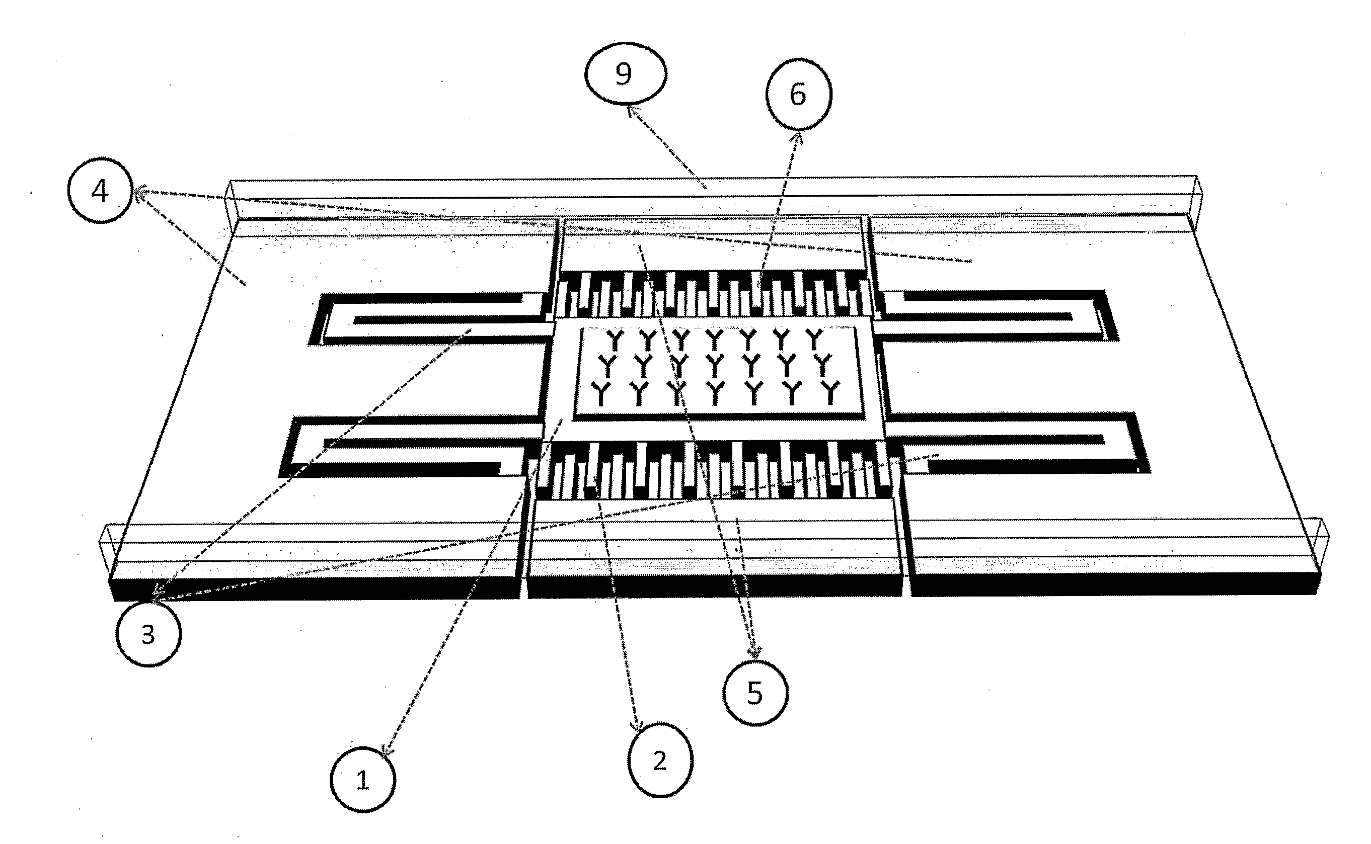
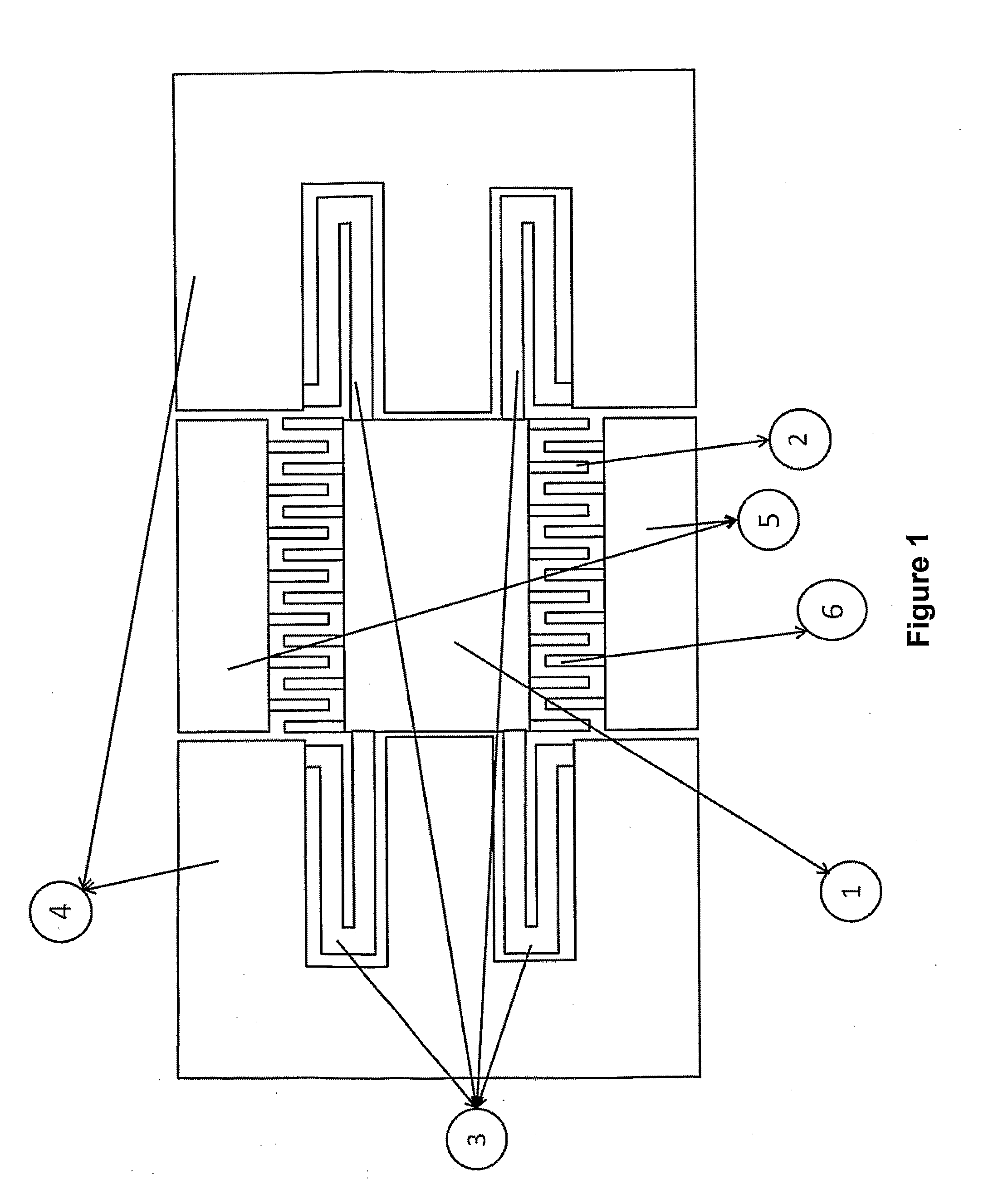
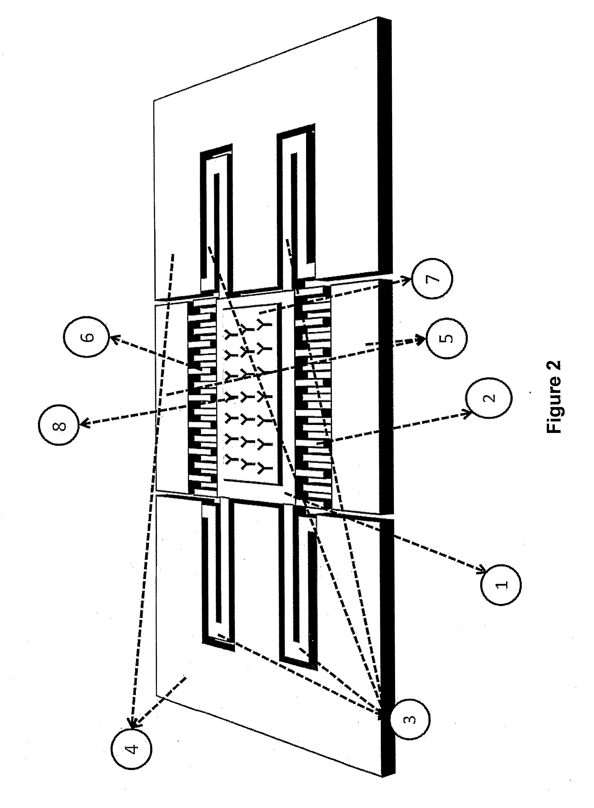
[0075]The resonator that can be placed onto the basis of the channel consists of a proof mass (1), the comb fingers fixed to proof mass (2), folded spring beams (3), channel floor and the mechanical ground (4), the stationary electrodes (5) and the comb fingers attached to the stationary electrodes (6). Channel floor and the mechanical ground (4) are attached to the bulk wafer via silicone dioxide, and they do not move. Folded spring beams (3), proof mass (1) and the comb fingers fixed to proof mass (2), are suspended. Parts of the resonator that can be placed onto the basis of the channel (1, 2, 3, 4, 5, and 6) are made of highly- or moderately-conductive single crystal silicon. The polymer coating (U.4) is...


PUM

PropertyMeasurementUnit
Volumeaaaaaaaaaa
Volumeaaaaaaaaaa
Volumeaaaaaaaaaa

Abstract

Laterally oscillating gravimetric sensing device embeddable under micro-fluidic channels and fabricated with micro-electro mechanical systems (MEMS) technology, which detects biological cells and analytes by measuring the change of mass attached on its surface is composed of four main groups, namely a resonator that can be placed onto the basis of the channel, components of the resonator bio-activation, a micro fluidic channel, and the microfabrication techniques, and its main components are the proof mass (1), comb fingers fixed to proof mass (2), folded spring beams (3), channel floor and mechanical soil (4), stationary electrodes (5), comb fingers attached to the stationary electrodes (6), golden film deposited onto the mass (7), immobilized biologic recognition molecules (8), and micro fluidic channel placed on resonator structure (9).

Description

RELATED FIELD OF THE INVENTION[0001]This invention represents a laterally oscillating gravimetric sensing device embeddable under micro-fluidic channels and fabricated with micro-electro mechanical systems (MEMS) technology, which detects biological cell and analytes by measuring the change of mass attached on its surface.BACKGROUND OF THE INVENTIONPrior Art[0002]A perturbation in the total mass of a resonating mechanical structure induces a shift in the frequency of the resonance. When combined with the micro-electro-mechanical systems, this method called gravimetric detection, may realize devices that can recognize target molecules or structures in the microscale. Gravimetric detectors are employed in many micro systems for biomedical and chemical applications. These can be found in various applications ranging from cell detection for diagnosis of cancer, AIDS or similar diseases to tests for bioterror agents in the air.[0003]Reported biomedical sensors using gravimetric detection...

Claims


Application Information

Patent Timeline
IPC IPC(8): G01N30/00
CPCG01G3/16G01N29/022G01N29/036Y10T436/11G01N2291/0256G01N2291/0427G01N29/222G01N27/00G01N29/02G01N33/48
Inventor KULAH, HALUKCIFTLIK, ATA TUNA
Owner MIKROBIYOSISTEMLER ELECTRONICS SAN & TIC AS
Learn More