
Portable touchless vital sign acquisition device

a technology of vital signs and acquisition devices, which is applied in the field of portable touchless vital sign acquisition devices, can solve the problems of limited localization value of ecg, difficult to localize sources directly from the electrical potential map, and reach a larger clinical utilization, so as to reduce the problem of cross-contamination, operate effectively, and achieve sufficient sensitivity

Inactive Publication Date: 2012-06-07
SKIDMORE FR M +2
View PDF10 Cites 27 Cited by
  • Summary
  • Abstract
  • Description
  • Claims
  • Application Information

AI Technical Summary

Benefits of technology

[0006]Magnetocardiography (MCG) is another tool to measure the electromagnetic signals arising from the heart. MCG also provides a high temporal resolution of signals arising from the heat, however the inventors have realized that the MCG has certain advantages over the ECG as the MCG is developed using sensitive biomagnetometers. Magnetic signals are not distorted or attenuated by passage through overlying tissue. One notable advantage of biomagnetometers realized by the inventors is that physical contact with a tissue is not necessary for a signal to be detected. This enables envisioning a number of applications in MCG, including rapid evaluation, or, for example, continuous monitoring in environments where skin contact is not desirable (e.g. burns) or possible (e.g. in utero fetal heart monitoring). Specialized personnel are not required to place leads, allowing for automated monitoring (for example, as is done with automated blood pressure cuffs in pharmacies). Furthermore, it is other applications are envisioned by the inventors, for example, placement of devices at health clubs or other non-medical settings for screening purposes. MCG can be used to non-invasively explore the fetal heart in utero. Additionally, MCG, unlike ECG, can be used for source localization. For example, multi-channel MCG can be used to noninvasively localize ectopic foci in atrial fibrillation, a procedure that commonly requires invasive testing.
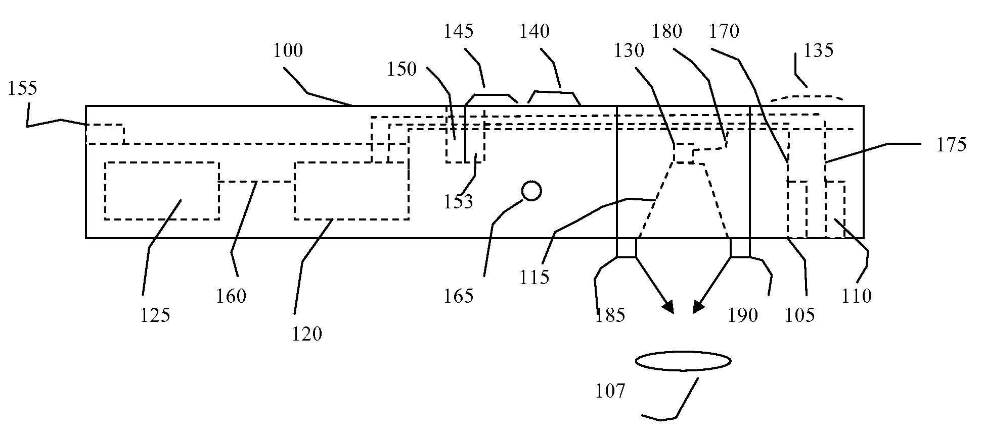
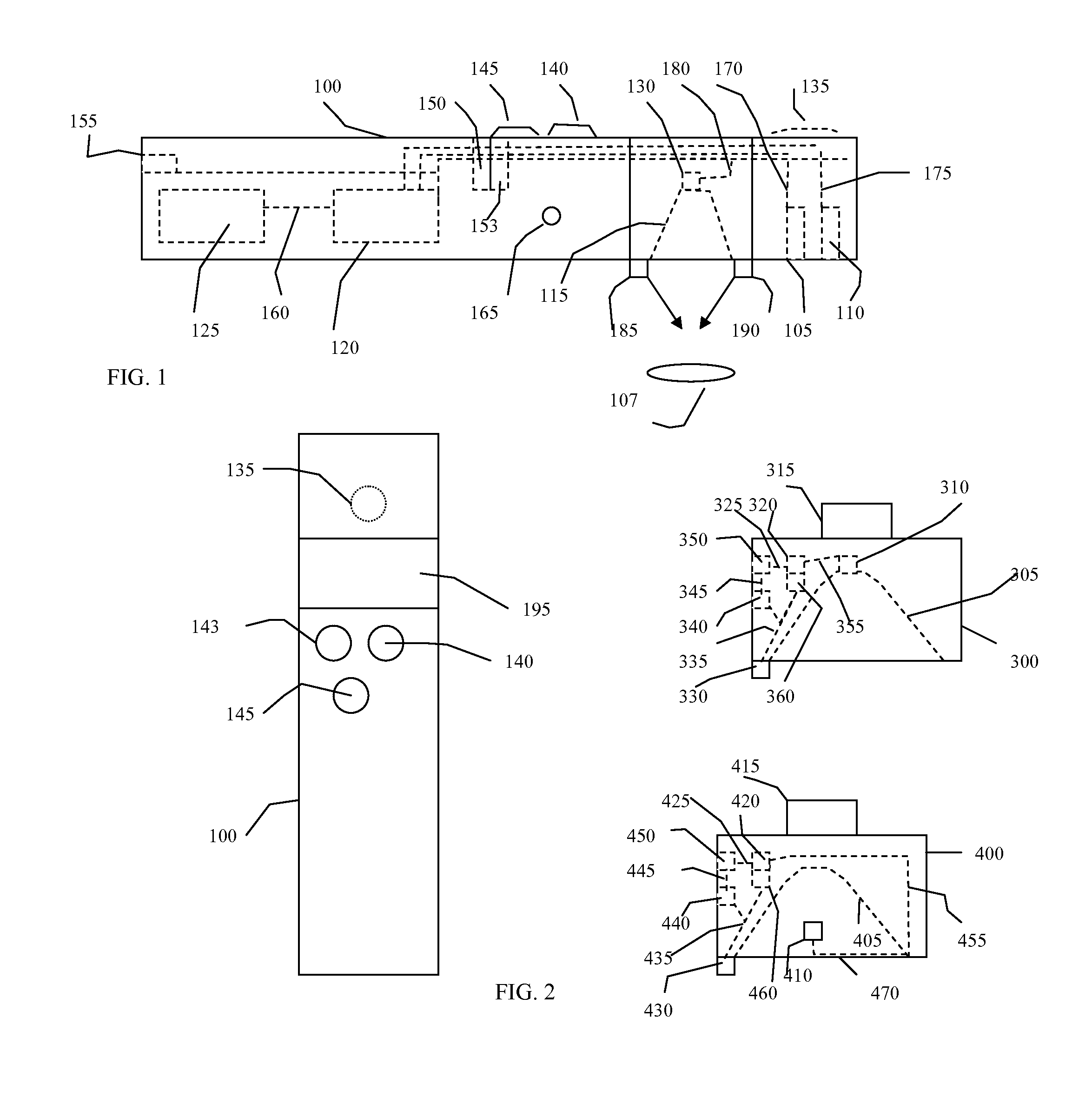
[0032]According to another embodiment, the invention pertains to an MCG device using a small scale (“meso-scale” (˜2 cm)) atomic magnetometer capable of measuring the cardiac signal. A meso-scale sensor will provide easily detectable signals, but still be small enough for a single sensor to be placed in a hand-held device. A sensor having sensitivity of 500 ft / √Hz or less is utilized. The embodiment pertains to a single-sensor device using optical magnetometers combined with active and passive shielding targeting a sensor sensitivity of 500 fT / √Hz or less. Embodiments of the invention are designed to be lightweight, portable, relatively inexpensive, and will and allow for easy patient repositioning. Dominant sources of system noise may be detected and minimized.

Problems solved by technology

However, the localizing value of ECG is limited.
Location of potential maxima on the skin may not overlay signal sources, making it difficult to localize source directly from the electrical potential map.
While these advantages would seem to make an MCG ideal as clinical measuring devices, magnetic monitoring has disadvantages that have prevented it from reaching a larger clinical utilization.
One significant disadvantage of biomagnetic signals is that signals are relatively weak compared with ambient magnetic disturbances.
SQUID-based systems are relatively expensive, requiring cryogenic cooling and bulky, rigid dewars.
In the past, magnetic shielding has also been a required significant expense associated with MCG systems.
However, these devices are still quite expensive in both capital and operational costs.
MCG has therefore remained largely a research device, limited to a few academic centers.
Non-contact detection of heart, lung, and other internal sounds is difficult using a simple microphone element.
Second, optical magnetometers do not require cryogenic cooling, leading to the potential of significant cost savings.
In this case, the focal point lies above the plane of the entrance to the parabola or in the parabola at a point not providing convenient mounting of the acoustic receiver at a hole in the base.

Method used


Image

  • Portable touchless vital sign acquisition device
  • Portable touchless vital sign acquisition device
  • Portable touchless vital sign acquisition device

Examples


Embodiment Construction

[0042]A non-contact MCG is anticipated as one embodiment. Additionally, a non-contact stethoscope, thermal sensor, or MCG could be utilized singly or in combination with each other, or included singly or together in other medical devices such as a fluoroscope, For example, a handheld, portable instrument comprising a non-contact stethoscope without a magnetometer or thermal sensor can provide a measure of acoustic signals without contacting a subject, while a non-contact thermal sensor as a single device can provide a rapid contactless temperature of a subject.

[0043]With respect to the non-contact stethoscope, a number of sound pickup techniques could be used for acoustic sensing. There are optically based sound pickup devices using lasers that could use the atomic magnetometer light source to develop the signal. More traditional directionally sensitive sound pickup devices may also be used. The non-contact stethoscope would optimally consist of a sound detection device such as a mi...


PUM


Abstract

Disclosed herein is a non-contact MCG is anticipated as one embodiment. Additionally, a non-contact stethoscope, thermal sensor, or MCG could be utilized singly or in combination with each other, or included singly or together in other medical devices such as a fluoroscope, For example, a handheld, portable instrument comprising a non-contact stethoscope without a magnetometer or thermal sensor can provide a measure of acoustic signals without contacting a subject, while a non-contact thermal sensor as a single device can provide a rapid contactless temperature of a subject

Description

RELATED APPLICATIONS[0001]This application claims the benefit of U.S. Ser. No. 61 / 145,67 filed Jan. 19, 2009, under 35 USC §119(e) which is incorporated herein by reference.INTRODUCTION[0002]The body produces acoustic, thermal, and electromagnetic signals that can be detected using appropriate instruments. For example, electrocardiography (ECG) has an important and well established role in the diagnosis and management of cardiovascular disease. The ECG provides a high temporal resolution (on the level of milliseconds or better) of signals arising from the human heart. However, the localizing value of ECG is limited. The strength of electrical signals arising from the heart is related to the boundaries and conductivity of underlying tissues, and to the proximity of sources to the electrode contacts. Location of potential maxima on the skin may not overlay signal sources, making it difficult to localize source directly from the electrical potential map. Similarly, cardiac or other sou...

Claims


Application Information

Patent Timeline
Patent Type & Authority Applications(United States)
IPC IPC(8): A61B7/04A61B5/01A61B5/02A61B5/05
CPCA61B5/02A61B7/04A61B5/04007A61B5/243
Inventor SKIDMORE, FRANK M.DAVIDSON, MARKDONDA, RUSSELL S.
Owner SKIDMORE FR M
Learn More