
Method for producing porous copper foil

a technology of porous copper foil and copper foil, which is applied in the direction of cell components, electrolysis components, instruments, etc., can solve the problems of reducing the capacity poor use efficiency of active substances, and reducing the performance of lithium ion secondary batteries, so as to achieve less roughness differences, improve performance, and reduce the influence of residual oxide films on porous copper foils

Active Publication Date: 2012-05-10
CHANG CHUN PETROCHEMICAL CO LTD
View PDF2 Cites 16 Cited by
  • Summary
  • Abstract
  • Description
  • Claims
  • Application Information

AI Technical Summary

Benefits of technology

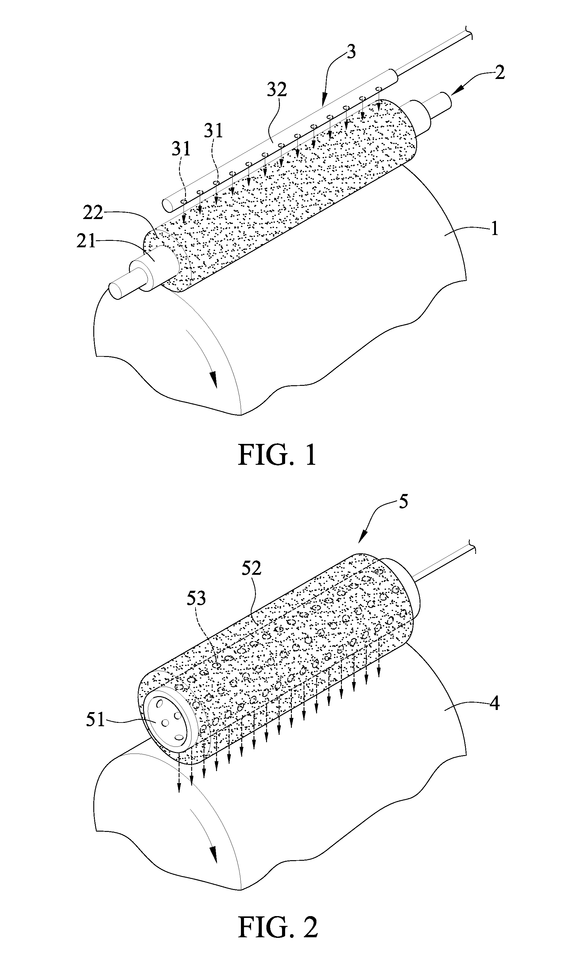
[0017]In one embodiment, the chromium-containing compound is transferred to the metal surface by a device including a metal roller, a sponge coated on the metal roller and an introducing component. The introducing component is disposed on the sponge for introducing the chromium-containing compound into the sponge, and may or may not contact the sponge. The sponge coated on the surface of the roller contacts the surface of the cathode for transferring the chromium-containing compound to the surface of the cathode. The transferring is performed by the device, such that splatter of the chromium-containing compound is avoided.
[0018]In one embodiment, the chromium-containing compound is transferred to the metal surface of the cathode by a device including a metal tube having a plurality of openings and coated with a sponge layer, wherein the sponge on the metal tube contacts the metal surface, and the chromium-containing compound is introduced into the metal tube, absorbed in the sponge layer via the openings and then transferred to the metal surface. The transferring is performed by such device, such that the chromium-containing compound is not easily splattering and an even transferring is achieved
[0020]In the method of the present invention, the chromium-containing compound is used on the cathode to form an oxide film, the chromium-containing compound such as chromic acid or dichromic acid is directly transferred on the cathode, and then electrolysis of copper is performed to form a porous copper foil. There is no need to apply voltage between the cathode and the oxidizing solution in the present invention. However, in the conventional method, an external voltage supply device is needed for the oxidation of the cathode. For example, a copper pyrophosphate bath is provided on the cathode for electroplating or an acidic acid solution (such as sulfuric acid) is provided to the cathode for electrolysis and oxidization. In comparison with the conventional method, the method of the present invention is simpler and cheaper.
[0021]Further, a porous copper foil is generally treated with rust prevention, in which chromic acid is frequently used in the rust prevention treatment for the copper foil. In the present invention, the chromium-containing compound is oxidized on the cathode, thus some chromium oxide may remain on the porous copper foil. Such residuals on the copper foil are similar to the material upon the rust prevention treatment. Therefore, the influence resulting from the residual oxide film on the porous copper foil is significantly reduced, and thus it is advantageous for the copper foil to be used in a lithium ion secondary battery. On the contrary, the coating of lipid is used in the conventional method; however, the residual lipid on the porous copper foil influences property of the surface of the porous copper foil, and is disadvantageous for the porous copper foil to be used in a lithium ion secondary battery.
[0022]In addition, in comparison with the prior art, there is less roughness difference between both sides of the porous copper foil in the present invention. It is clear that both sides of the porous copper foil of the present invention have similar surface properties and similar coating thicknesses of carbon material, such that a lithium ion secondary battery having the porous copper foil of the present invention has better performance. Accordingly, in comparison with the prior art, the porous copper foil of the present invention is more advantageous for the formation of a lithium ion secondary battery.

Problems solved by technology

When the thickness of the coated carbon material on the copper foil is not even, the usage efficiency of the active substance (i.e. lithium ions) is poor, and thus the capacity of the battery is reduced.
On the contrary, when both sides of the copper foil have significantly different surface profiles, the both sides of the copper foil have different roughness and uniformity, and the resulting lithium ion secondary battery has reduced performance.
It is clear that the usage of porous copper foil overcomes the reduced performance resulting from the uneven coating of carbon material.
However, the formation of a porous copper foil usually results in the increased roughness Rz of Matte side (surface of the copper foil without contacting the drum cathode); and when there is a severe difference in the roughness Rz between the Matte side and Shiny side (surface of the copper foil contacting the drum cathode), uneven coating of carbon material occurs and thus performance of the lithium ion secondary battery increased by the porous copper foil is offset.
In addition, the conventional method for forming a porous copper foil is complicated, wherein a thin copper layer is formed on the surface of a cathode by electrolysis, and the surface of the cathode is treated by coating with lipid or applying voltage with an acidic solution to form an oxide film on the surface of the cathode.
Moreover, the residual lipid or residual oxide film may influence the surface quality of the copper foil, and further affect efficacy of the secondary battery.

Method used


Image

  • Method for producing porous copper foil
  • Method for producing porous copper foil
  • Method for producing porous copper foil

Examples


example 1

[0039]The chromium-containing compound was transferred by the transfer device shown in FIG. 1, wherein the chromium-containing compound was chromic acid. In Examples 1-1 to 1-5, the concentrations of chromic acid were 1.2, 0.5, 2.0, 3.0, 5.0 (g / L), respectively. In each Example, the chromic acid was introduced into an introducing component 3, which may be a PVC tube, at 100 mL / hr, then dropped on the sponge 22 via the openings 31 of the introducing component 3, and was transferred to the surface of the cathode.

[0040]Operation conditions for electrolysis of the copper foil:

[0041]Composition of electrolysis bath:

[0042]Concentration of copper sulfate: 290 g / L

[0043]Concentration of sulfuric acid: 100 g / L

[0044]Temperature of electrolytic solution: 40° C.

[0045]Current density: 33 A / dm2

example 2

[0046]The device and operation conditions in this embodiment are similar to those of Embodiment 1 except that the chromium-containing compound is sodium dichromate (1.2 g / L).

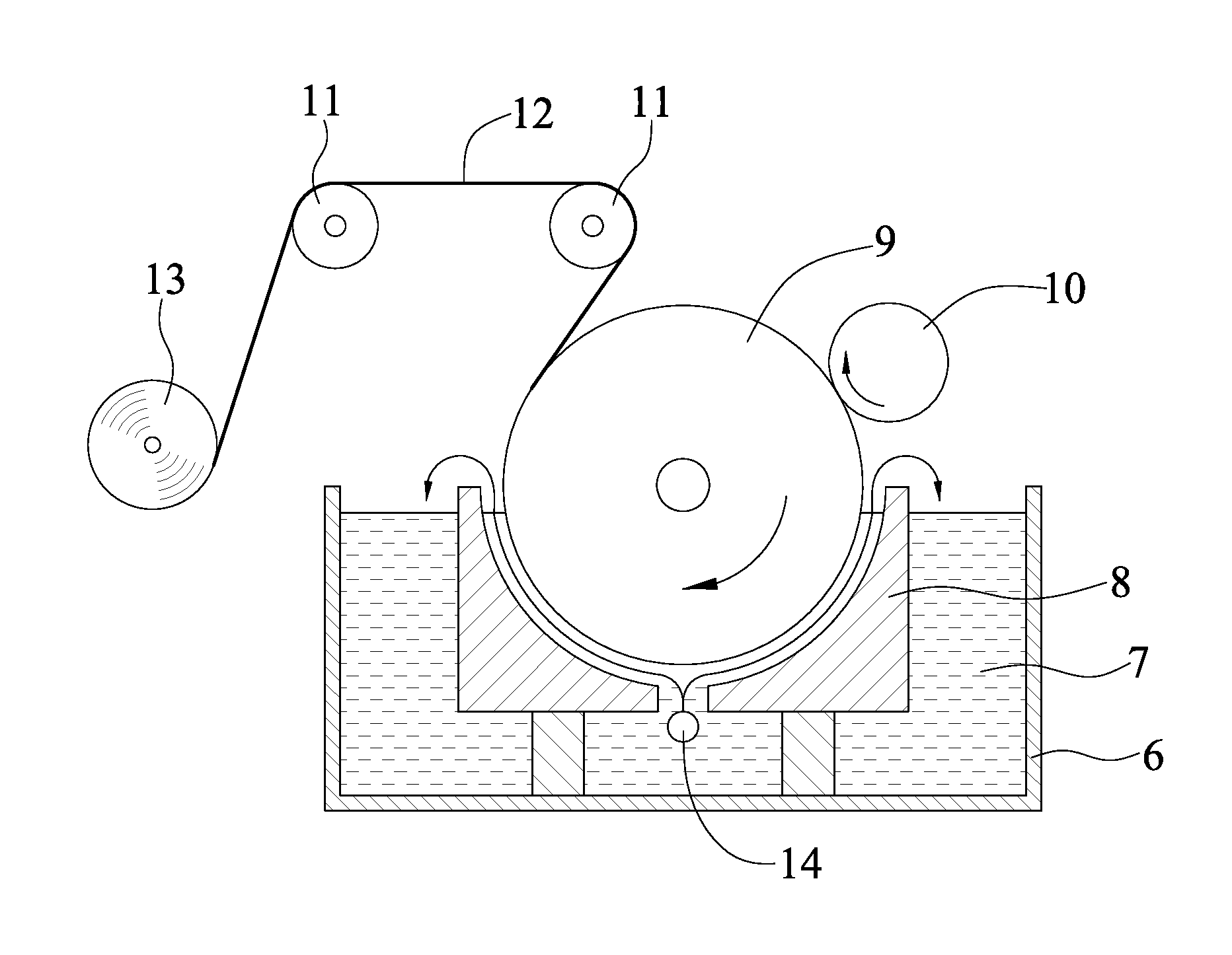
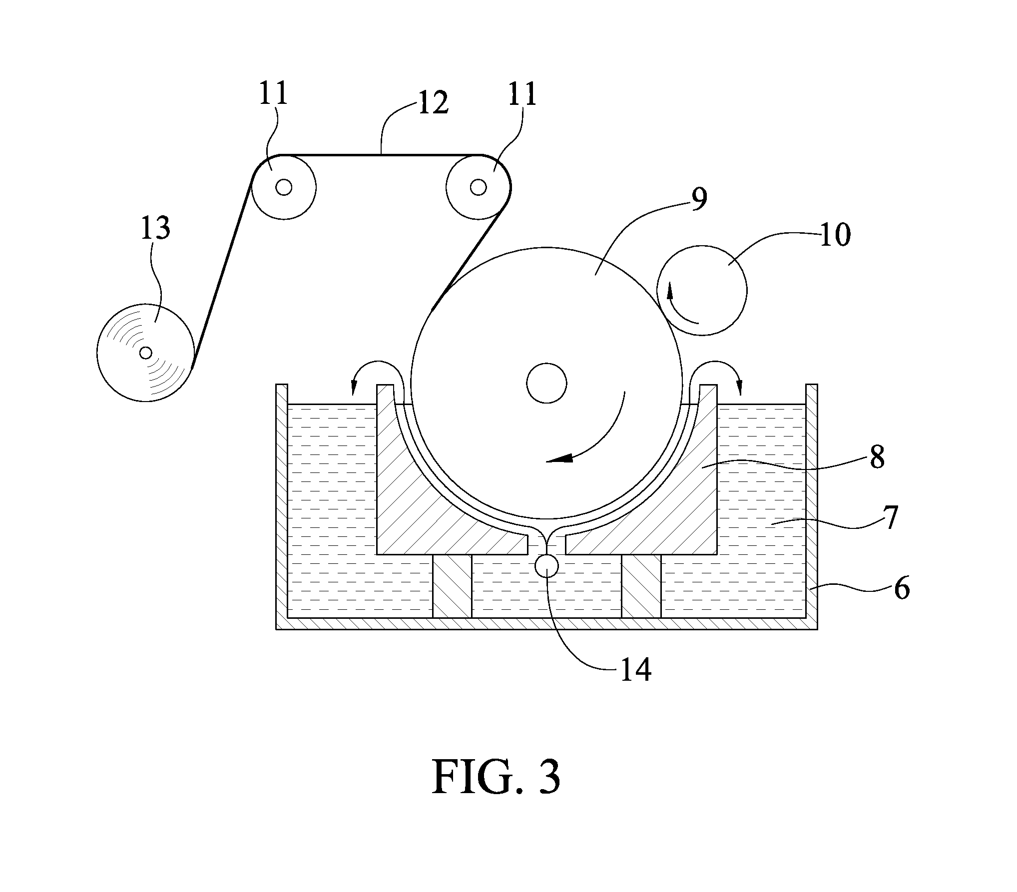
[0047]The property of the porous copper foils obtained from Example 1 and Example 2 are listed in Table 1. FIG. 4A to FIG. 4C are images showing the pores of the porous copper foil prepared in Example 1-1 by electron microscope.

TABLE 1Chromium-ThicknessPore densityDiameterRz ofRz ofRz differenceExamplecontainingConcentrationof copper foilof copper foilof poreShiny sideMatte sidebetween both sidesNo.compound(g / L)(μm)(1 / mm2)(μm)(μm)(μm)(μm)1-1Chromic1.2102081-301.173.582.41acid1-2Chromic0.5101171-201.102.951.85acid1-3Chromic2.0101761-301.143.802.66acid1-4Chromic3.0101311-301.083.702.62acid1-5Chromic5.010721-301.103.812.71acid2Sodium1.2101801-301.214.573.36dichromate

[0048]As shown in Table 1, in the present invention, the chromium-containing compound is directly provided to form an oxide film on a cathode (without ...


PUM

PropertyMeasurementUnit
thicknessaaaaaaaaaa
roughnessaaaaaaaaaa
pore densityaaaaaaaaaa

Abstract

The present invention provides a method for producing a porous copper foil. The method of the present invention includes the steps of forming an oxide film by providing a chromium-containing compound to a metal surface of a cathode; forming a copper foil on the oxide film by performing electrolysis of copper; and removing the copper foil from the metal surface of the cathode. The method of the present invention is simple and time-saving, and the porous copper foil of the present invention has reduced roughness difference between both sides of the porous copper foil.

Description

BACKGROUND OF THE INVENTION[0001]1. Field of the Invention[0002]The present invention relates to methods for producing a copper foil, and more particularly, to a method for producing a porous copper foil.[0003]2. Description of Related Art[0004]Recently, notebook computers, mobile phones, PDA are developed to be minimized and lightened, and batteries thereof thus need to be minimized Nonaqueous electrolyte secondary batteries, such as lithium ion secondary batteries, have high energy density and high capacity, and thus are widely used in the above mentioned electronic devices.[0005]In lithium ion secondary batteries, lithium transition-metal composite oxide used as material of a positive electrode (cathode) and carbon material such as graphite used as a negative electrode (Anode) are respectively mixed with a conductive agent and a binder to form a paste for coating respective collectors such as an aluminum foil and a copper foil, so as to form a positive electrode and a negative el...

Claims


Application Information

Patent Timeline
Patent Type & Authority Applications(United States)
IPC IPC(8): C25C1/12
CPCC25C1/12H01M10/052H01M4/661C25D1/04Y02E60/10C25D1/20C25D7/06
Inventor TSAI, CHEN-PINGCHOU, JUI-CHANGCHENG, KUEI-SEN
Owner CHANG CHUN PETROCHEMICAL CO LTD
Learn More