
Method and tool for manufacturing face gears

Active Publication Date: 2012-04-26
GLEASON WORKS
View PDF25 Cites 21 Cited by
  • Summary
  • Abstract
  • Description
  • Claims
  • Application Information

AI Technical Summary

Problems solved by technology

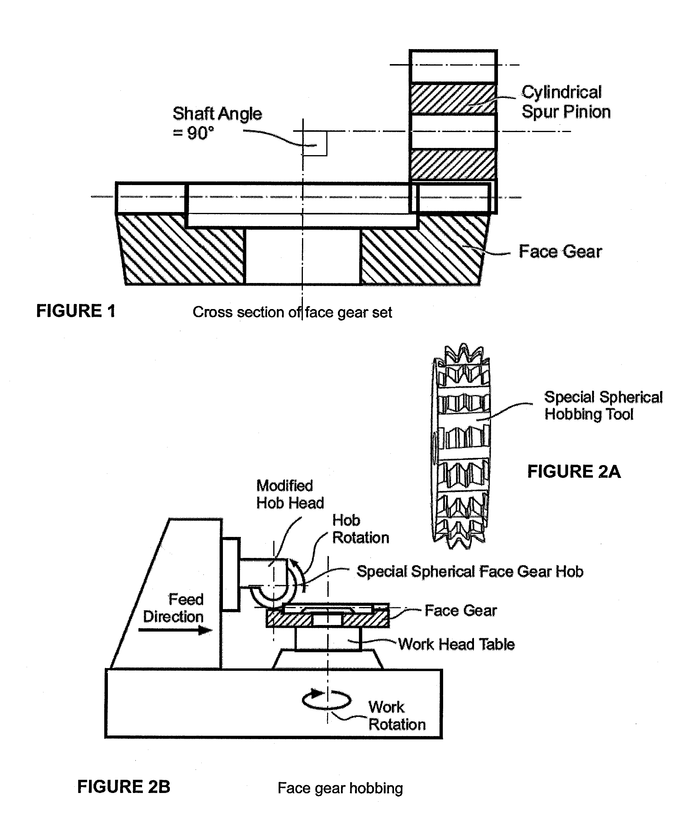
To date, methods of manufacturing face gears have been complicated, with special tools dedicated to a single design applied on machine tools which are usually modified cylindrical gear manufacturing machines.
Presently, face gear soft machining methods depend on job specific, special tools, which are expensive and not flexible regarding their use for other jobs or for optimizations.
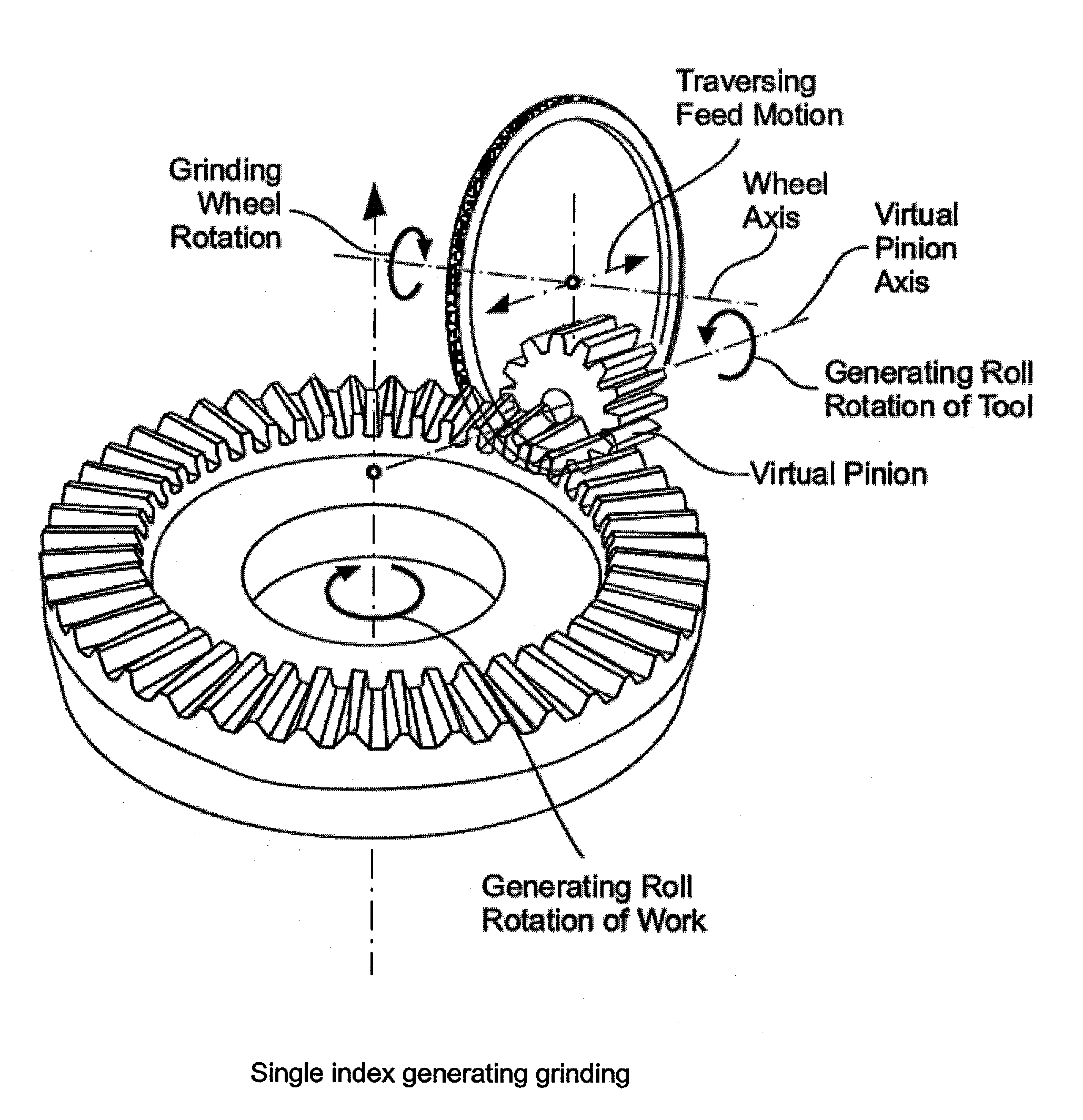
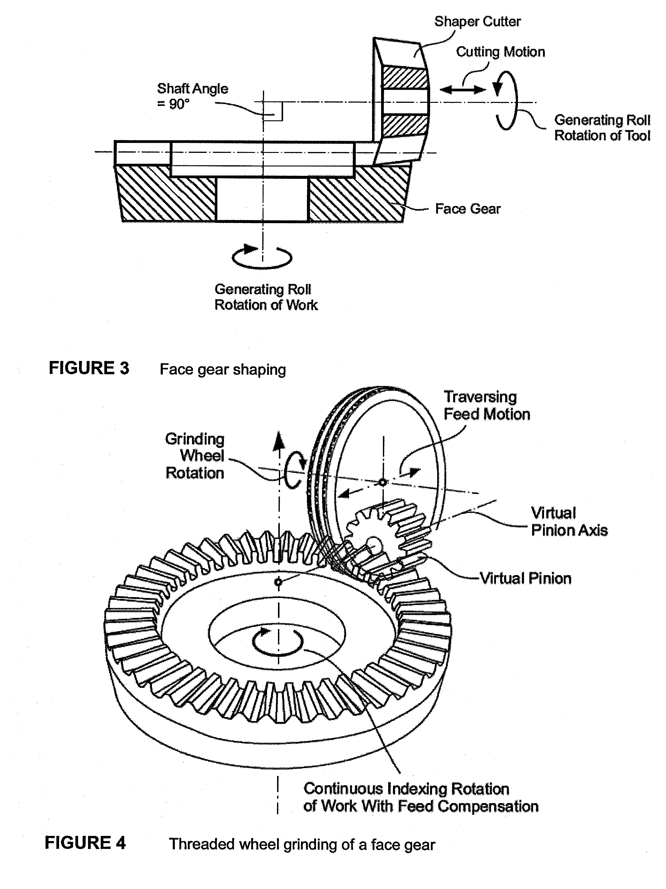
Two of the more common face gear hard finishing methods use either a very complex tool geometry which is difficult to dress and requires a long dressing time (threaded wheel grinding), or a complicated and time consuming generating roll, combined with a feed motion in face width direction (single index generating grinding).
Skiving with a special hob or a shaper cutter made from carbide material provides reasonable cutting times but requires a tool which is not only expensive but also not readily available or not available at all.
Face gear honing requires, for example, a heat treated, ground and CBN coated pinion, which is expensive, not flexible and depends on a rather large pinion offset (equal the required offset between face gear and mating cylindrical pinion) for good chip removal, which limits the application to face gear sets which have such a high offset.

Method used


Image

  • Method and tool for manufacturing face gears
  • Method and tool for manufacturing face gears
  • Method and tool for manufacturing face gears

Examples


Embodiment Construction

[0032]Before any features and at least one construction of the invention are explained in detail, it is to be understood that the invention is not limited in its application to the details of construction and the arrangements of the components set forth in the following description or illustrated in the drawings. The invention is capable of other constructions and of being practiced or being carried out in various ways. Also, it is understood that the phraseology and terminology used herein is for the purposes of description and should not be regarded as limiting.

[0033]The use of “including”, “having” and “comprising” and variations thereof herein is meant to encompass the items listed thereafter and equivalents thereof as well as additional items. The use of letters to identify elements of a method or process is simply for identification and is not meant to indicate that the elements should be performed in a particular order.

[0034]Although references may be made below to directions...


PUM

PropertyMeasurementUnit
Angleaaaaaaaaaa
Shapeaaaaaaaaaa

Abstract

A cutter disk having cutting blades oriented on its circumference with the cutting edges of the blades oriented perpendicular to the axis of rotation of the cutter disk thereby representing a plane which can be oriented to a work piece (e.g. face gear) under an angle equal to the pressure angle of the mating face gear set's pinion, and, which can be rotated around a virtual pinion axis to generate a tooth flank on the work piece.

Description

[0001]This application claims the benefit of U.S. Provisional Patent Application No. 61 / 230,785 filed Aug. 3, 2009 the entire disclosure of which is hereby incorporated by reference.FIELD OF THE INVENTION[0002]The present invention is directed to the manufacturing of gears and in particular, to a method and tool for manufacturing face gears.BACKGROUND OF THE INVENTION[0003]Face gears are ring gears with a face angle (and root angle) equal to the shaft angle between the face gear and it's mating member. The mating member is a regular cylindrical spur or helical pinion. Standard face gears have a face angle of 90° which corresponds to a shaft angle of also 90° (such 90° gears are also known as “crown” gears).[0004]To date, methods of manufacturing face gears have been complicated, with special tools dedicated to a single design applied on machine tools which are usually modified cylindrical gear manufacturing machines. Such methods for the soft manufacturing of face gears include:[000...

Claims


Application Information

Patent Timeline
IPC IPC(8): B23F5/06
CPCB23F15/06Y10T409/105883B23F23/006B23F21/16B23F5/02B23F5/06Y10T409/103816Y10T409/103975B23F5/20
Inventor STADTFELD, HERMANN J.
Owner GLEASON WORKS
Learn More