
Method and Apparatus for Removal of The Double Indication of Defects in Remote Eddy Current Inspection of Pipes

a technology of eddy current inspection and double indication, which is applied in the direction of seismology for waterlogging, borehole/well accessories, instruments, etc., can solve the problems of affecting the functionality of the casing, the inability of the caliper to be used, and the possibility of corrosion. to achieve the effect of lowering the signal-to-noise ratio

Inactive Publication Date: 2012-04-19
SCHLUMBERGER TECH CORP
View PDF3 Cites 49 Cited by
  • Summary
  • Abstract
  • Description
  • Claims
  • Application Information

AI Technical Summary

Benefits of technology

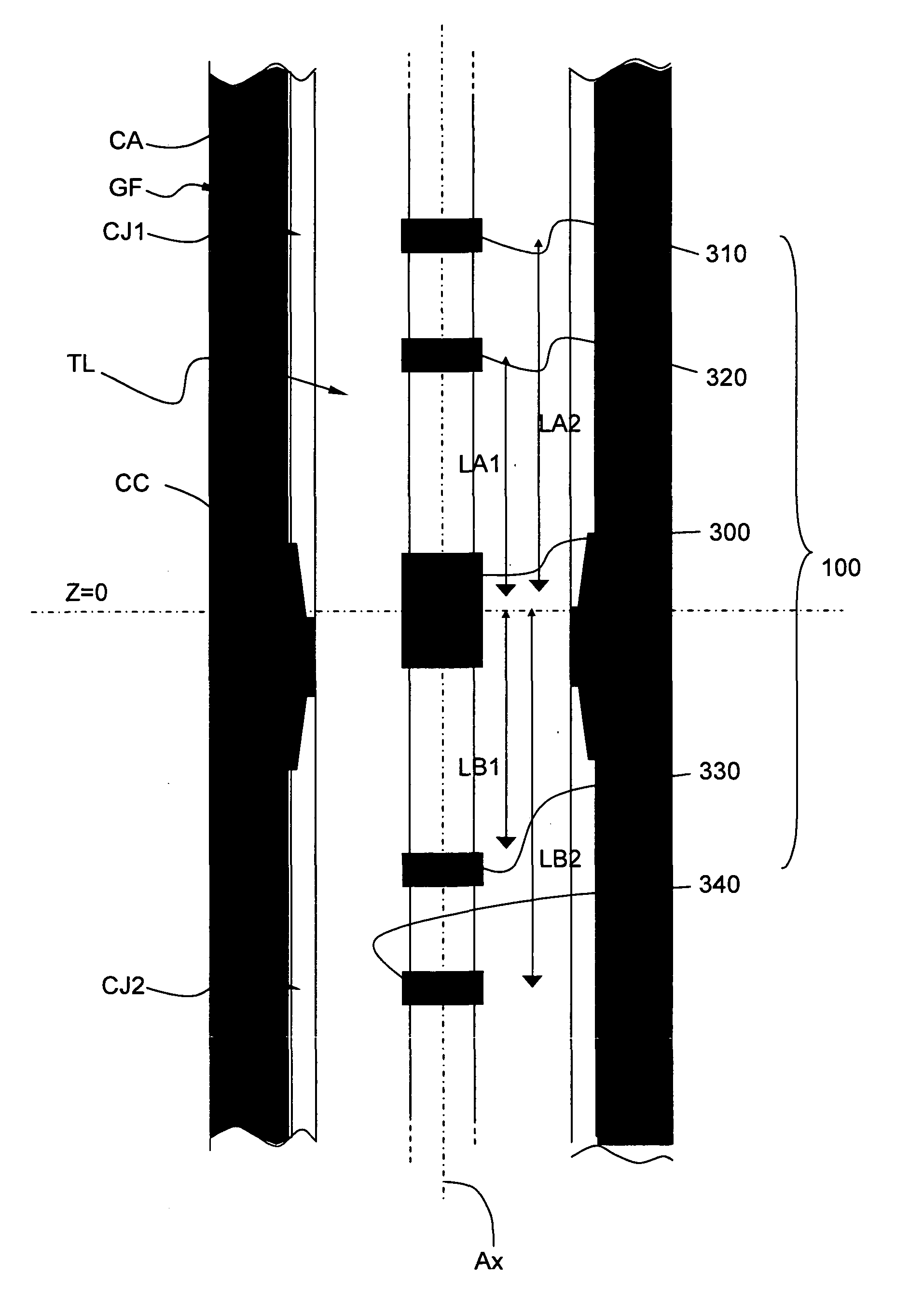
[0018]Generally, this apparatus for measuring defects in a well bore pipe using remote field eddy current measurement provides a transmitter coil and a plurality of receiver coils in spaced axial relationship from each other; a circuit generating a transmitter current and sensing a receiver voltage at each of the plurality of receiver coils collecting a convoluted signal proportional to the thickness of the pipe adjacent each receiver coil; and, a data analysis circuit which deconvolutes each sensed signal to remove ghost-image signals from such receiver signal. Preferably, the receiver coils are symmetrically located on opposing sides of the transmitting coil. A preferred arrangement for this apparatus for measuring defects in a pipe using remote field eddy current measurement comprises a transmitter providing a selectable low frequency electromotive force; a pair of receiver coils spaced longitudinally on a first side of the transmitter and a pair of receiver coils spaced longitudinally on a second side of the transmitter each pair of coils symmetrically matched with the similarly situated receiver coil on the opposing side of the transmitter; a circuit for correlating the transmitter current and the receiver voltages, as the apparatus is moved through the pipe; thereby permitting said circuit to measure phase deviations of a transimpedance as the apparatus moves past the same point in the pipe allowing the duplicate image to be eliminated and the impulses transmitted and received by the transmitter to be averaged lowering a signal to noise ratio for the measurement of receiver voltage.
[0019]The apparatus allows a method for removing ghost defects from a remote field eddy current sensing device comprising generating from a transmitter an eddy current on a well bore tubular outer surface; detecting the eddy current signal with more than one remote receiver; generating an eddy current signal on a well bore tubular outer surface from an incrementally different position; detecting the eddy current with the more than one remote receiver from the incrementally different position; determining a linear combination of eddy current signals detected by the more than one remote receiver to eliminate ghost defects in such received signals.

Problems solved by technology

Nevertheless, in harsh environment, the casing may be subject to corrosion that may affect its functionality.
The mechanical calipers cannot be used for the determination of casing thickness, cannot distinguish non-metallic deposits on the casing from the metallic casing itself, and may initiate corrosion by scratching the casing surface.
The ultrasonic tool cannot be used when the casing transports a fluid mixture comprising a certain quantity of gas relatively to liquid, and provides deteriorated reflected signals in the presence of surface roughness that typically arise in corroded casing.
The combinations of casings and tubing used in hydrocarbon wells often exhibit varying pipe diameters that render the requirements of sufficiently strong and well-coupled magnetic flux difficult to maintain.
Furthermore, magnetic flux-leakage tools are not suitable for measurements of gradual thinning of pipes.

Method used


Image

  • Method and Apparatus for Removal of The Double Indication of Defects in Remote Eddy Current Inspection of Pipes
  • Method and Apparatus for Removal of The Double Indication of Defects in Remote Eddy Current Inspection of Pipes
  • Method and Apparatus for Removal of The Double Indication of Defects in Remote Eddy Current Inspection of Pipes

Examples


Embodiment Construction

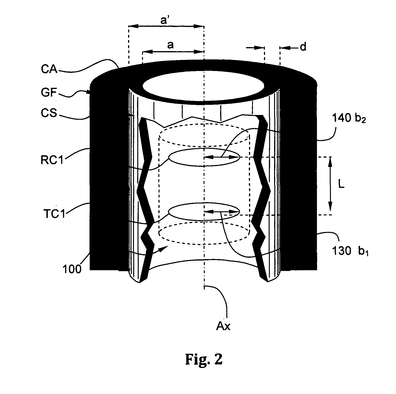
[0029]FIG. 2 shows schematically the measuring arrangement 1 according to a preferred embodiment of the invention. The measuring arrangement 1 is fitted within the logging tool TL illustrated in FIG. 1.

[0030]In the preferred embodiment of the invention all measurements of the tool are based on the determination of the transimpedance Z which is defined as the mutual impedance between the transmitter current I and the receiver voltage V of a given transmitter-receiver pair:

Z=VIEq.(1)

The tool response may be compared to that of a poorly coupled and lossy transformer where the transmitter of the primary circuit induces a voltage in the receiver coil of the secondary circuit. This mutual inductance coupling is composed of flux-coupling through the medium inside the casing and of contributions by flux passing through the metal and outside of the pipe. The electromagnetic field is strongly affected by eddy-currents inside the metal, which flow circumferentially virtually uninhibited. The m...


PUM


Abstract

The apparatus employs the remote field eddy-current (RFEC) inspection technique to electromagnetically measure physical parameters of a metallic pipe. RFEC devices inserted into and displaced along a cylindrical pipes may be used to measure the ratio of pipe thickness to electromagnetic skin-depth and thus allow for the non-invasive detection of flaws or metal loss. Typically these RFEC thickness measurements exhibit a so-called double-indication of flaws, an undesired artifact due to a double-peaked geometrical sensitivity function of the device. The method describes a means by which this double indication artifact may be removed by an appropriate processing of RFEC measurements performed by an apparatus specifically designed for this purpose. The invention is particularly well designed for applications in the oilfield industry.

Description

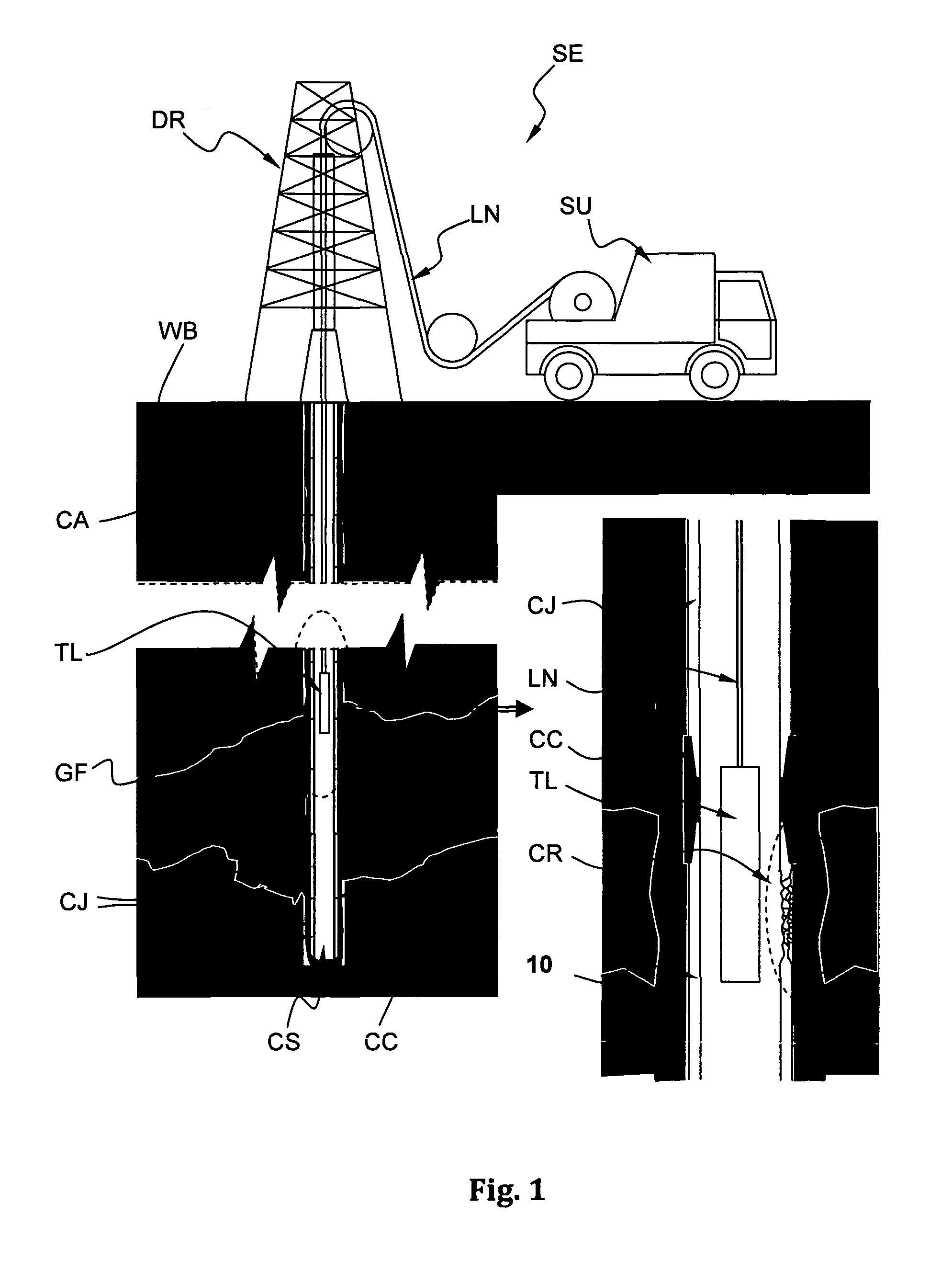
BACKGROUND[0001]This application relates to a method and apparatus for detecting corrosion loss in well bore tubulars; more specifically, this method and apparatus relate to the removal of double indication of defects from varying tubular geometries while performing remote field eddy current non-destructive inspection of such tubulars.Introduction and Prior Art[0002]FIG. 1 schematically shows a typical onshore hydrocarbon well location and surface equipments SE above a hydrocarbon geological formation GF after a well-bore WB drilling operation has been carried out, after a casing string CS has been run and after cementing operations have been carried out for sealing the annulus CA (i.e. the space between the well-bore WB and the casing string CS).[0003]Typically, the casing string comprises a plurality of casing joints, two casing joints being coupled together by a casing collar. The casing string stabilizes the well-bore.[0004]The casing joint is a length of steel pipe, generally a...

Claims


Application Information

Patent Timeline
Patent Type & Authority Applications(United States)
IPC IPC(8): G01B7/06G06F19/00
CPCE21B47/082G01N27/9046G01B7/10E21B47/085E21B49/003G01N27/902G01N27/9073G01N27/9086
Inventor LEGENDRE, EMMANUELBRILL, THILO M.ROSTHAL, RICHARD A.MINERBO, GERALD N.
Owner SCHLUMBERGER TECH CORP
Learn More