
Amplitude control circuit, polar modulation transmission circuit, and polar modulation method

a technology of polar modulation transmission circuit and polar modulation, which is applied in the direction of modulation, transmission monitoring, baseband system details, etc., can solve the problems of deterioration of accuracy, and deterioration of modulation characteristic, so as to suppress the variation of offset voltage of an amplification section

Inactive Publication Date: 2012-04-05
PANASONIC CORP
View PDF4 Cites 3 Cited by
  • Summary
  • Abstract
  • Description
  • Claims
  • Application Information

AI Technical Summary

Benefits of technology

[0014]According to an amplitude control circuit, polar modulation transmission circuit, and polar modulation method of the present invention, by setting an amplitude control circuit as a differential circuit configuration, and, further, providing level control section that controls the level of a differential amplitude signal according to transmitting power information, the first offset calculation section that gives DC offset to match transmitting power information to a differential amplitude signal output from a level control section, and a differential single conversion section that performs differential single conversion to a differential amplitude signal output from the first offset calculation section and outputs the result, the noise applied to a positive phase signal and a negative phase signal in a differential amplitude signal is cancelled each other, so that it is possible to decrease the output noise and suppress degradation of receiving sensitivity.
[0015]In addition, by detecting the output of the first offset calculation section, the present invention calculates the gain from a DA converter to an offset calculation section, adjusts the reference voltage from a reference voltage generation section in order to make the value to be the defined value, and supplies the result to a DA converter and an offset calculation section, so that it is possible to correct the gain from a DA converter to an offset calculation section. As a result, even when a differential signal is used in an amplitude control section of a polar modulation transmission circuit, it is possible to suppress the variation of offset voltage of an amplification section.

Problems solved by technology

In this way, there is a limit to adjust the value of DC voltage (V3), so that the accuracy may be deteriorated.
This is equivalent to adding unnecessary offset to the amplitude data, and by this means the modulation characteristic may be deteriorated.
Therefore, the result of the study has been acquired that by using a differential circuit configuration as in FIG. 3, the zero level of amplitude data varies, and by this means that the modulation characteristic may be deteriorated.

Method used


Image

  • Amplitude control circuit, polar modulation transmission circuit, and polar modulation method
  • Amplitude control circuit, polar modulation transmission circuit, and polar modulation method
  • Amplitude control circuit, polar modulation transmission circuit, and polar modulation method

Examples


embodiment 1

[1] Configuration

[0094]FIG. 10, where parts that are the same as in FIG. 3 are assigned the same reference numerals as in FIG. 3, shows a configuration example of a polar modulation transmission circuit according to embodiment 1 of the present invention.

[0095]Polar modulation transmission circuit 200 has amplitude phase extraction section 110, amplitude control section 210, phase modulation section 130, amplification section 140, and output terminal 150.

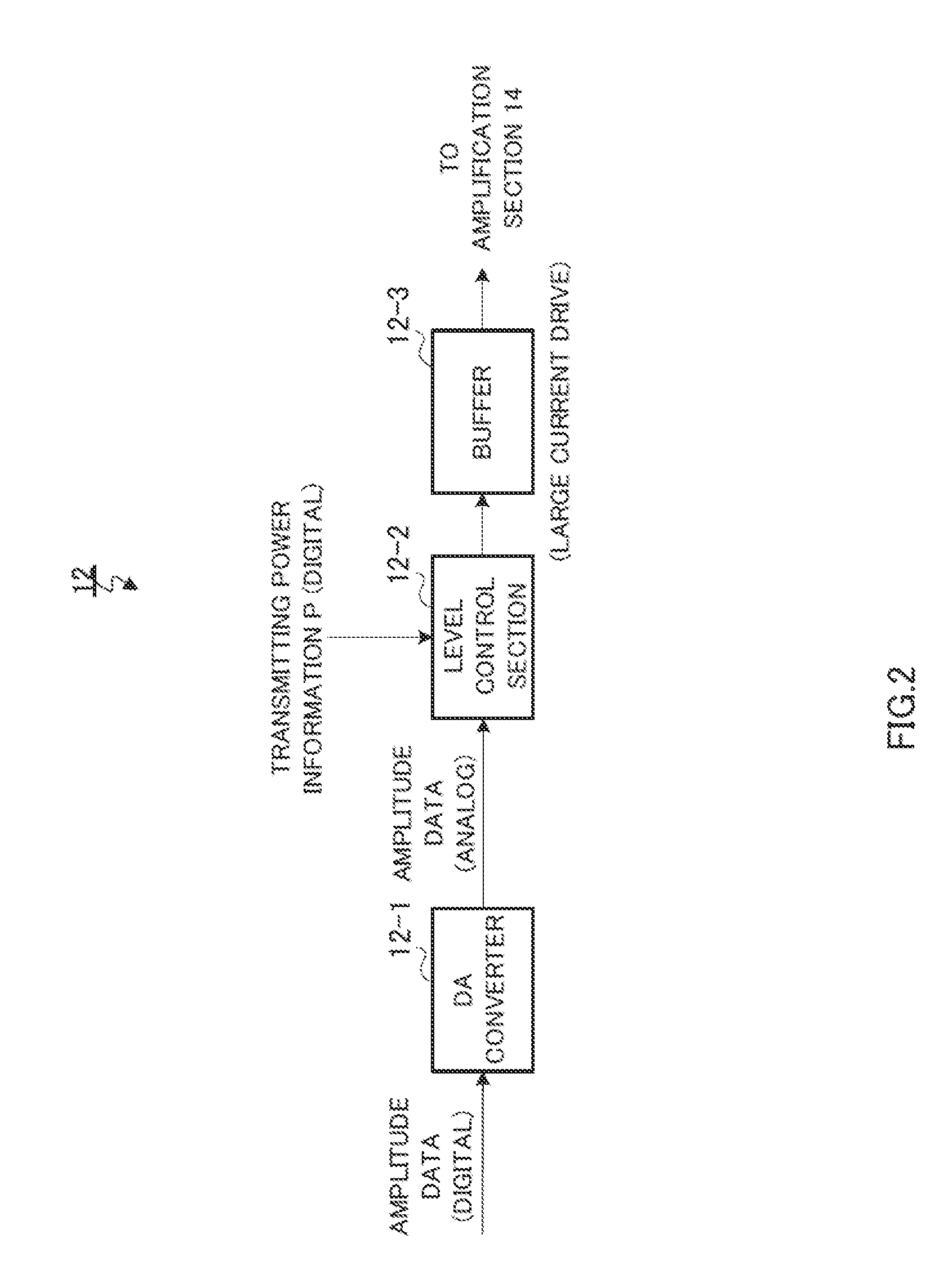
[0096]Amplitude control section 210 has DA converter 121, level control section 122, offset calculation section 123, differential single conversion section 124, reference voltage generation section 211, and reference voltage adjusting section 212. Compared to amplitude control section 120 of FIG. 3, reference voltage generation section 211 and reference voltage adjusting section 212 are added to amplitude control section 210 of polar modulation transmission circuit 200 of-the present embodiment.

[0097]Reference voltage adjusting secti...

embodiment 2

[0119]The present embodiment presents a configuration that can move output the characteristics closer to the ideal operation regardless of the gain of level control section 122.

[0120]Here, when a configuration such as embodiment 1 is applied, as shown in FIG. 13, when the gain of level control section 122 is maximum, it is possible to perfectly match the output characteristic of offset calculation section 123 and differential single conversion section 124 to an ideal operation. Meanwhile, as shown in FIG. 14, when the gain of level control section 122 is half of the maximum gain, the output characteristic of offset calculation section 123 and differential single conversion section 124 is slipped off as shifted from the ideal operation.

[0121]This is because the influence by reference voltage adjusting section 212 multiplying the reference voltage of reference voltage generation section 211 by 1 / 1.2 times reflects in offset calculation section 123. As described above, from power infor...

embodiment 3

[0130]FIG. 16, where parts that are the same as in FIG. 10 are assigned the same reference numerals as in FIG. 10, shows a configuration example of a polar modulation transmission circuit according to the present embodiment. Polar modulation transmission circuit 400 of the present embodiment is preferable especially when a power amplifier using a hetero bipolar transistor (HBT) is used for amplification section 140.

[0131]Compared to amplitude control section 210 of embodiment 1, amplitude control section 410 of the present embodiment has a configuration where second offset calculation section 411 is added between first offset calculation section 123 and differential single conversion section 124. In order to separate offset calculation sections 123 and 411, hereinafter referred to the former as the first offset calculation section and the latter as the second offset calculation section.

[0132]To second offset calculation section 411, offset information Q (which is often represented b...


PUM


Abstract

A reference voltage adjustment unit (212) calculates gain from a DA converter (121) to an offset calculating unit (123) by detecting the output of the offset calculating unit (123), adjusts the reference voltage (V3) from a reference voltage generation unit (211) so that the value becomes a predetermined value, and feeds the post-adjustment reference voltage (V4) to the DA converter (121) and offset calculating unit (123). Due to this, the gain from the DA converter (121) to the offset calculating unit (123) can be corrected. Fluctuation in the lower limit level of the output of a differential-to-single conversion unit (124) can be minimized as a result, so, the addition of unnecessary offset to the amplitude data at the amplifier unit (140) can be minimized. Thus, deterioration in modulation characteristics when the amplitude control unit (210) takes a differential circuit configuration can be minimized.

Description

TECHNICAL FIELD[0001]The present invention relates to an amplitude control circuit, polar modulation transmission circuit, and polar modulation method used for a communication device including, for example, a mobile telephone and a wireless LAN. More specifically, the present invention relates to an amplitude control circuit, polar modulation transmission circuit, and polar modulation method that operate with high efficiency and low distortion.BACKGROUND ART[0002]A communication device such as a mobile telephone and a wireless LAN is required to maintain linearity of a transmission signal over a wide range of output level and operate at low power consumption at the same time. In this communication device, a transmission circuit that operates with high efficiency and low distortion is used. A conventional transmission circuit will be described below.[0003]As a conventional transmission circuit, for example, there is a transmission circuit (hereinafter referred to as “quadrature modul...

Claims


Application Information

Patent Timeline
Patent Type & Authority Applications(United States)
IPC IPC(8): H04L27/04
CPCH03F3/45475H03F3/45968H03F2200/375H03C5/00H03F2203/45594H04B1/0483H03F2203/45528
Inventor IKEDO, TAICHI
Owner PANASONIC CORP
Learn More