
Magnetic recording medium

Active Publication Date: 2012-02-23
FUJIFILM CORP
View PDF4 Cites 147 Cited by
  • Summary
  • Abstract
  • Description
  • Claims
  • Application Information

AI Technical Summary

Benefits of technology

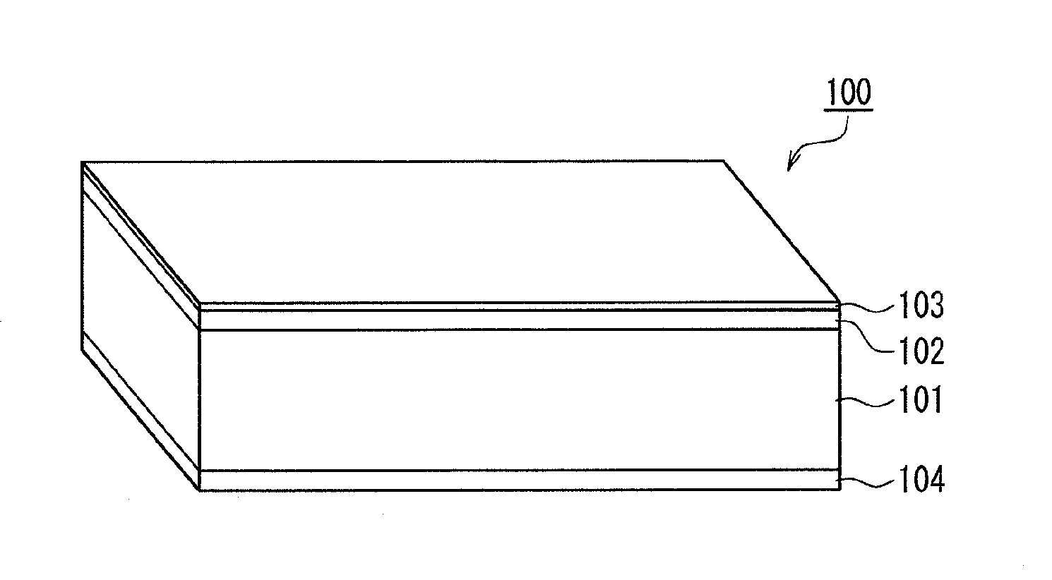
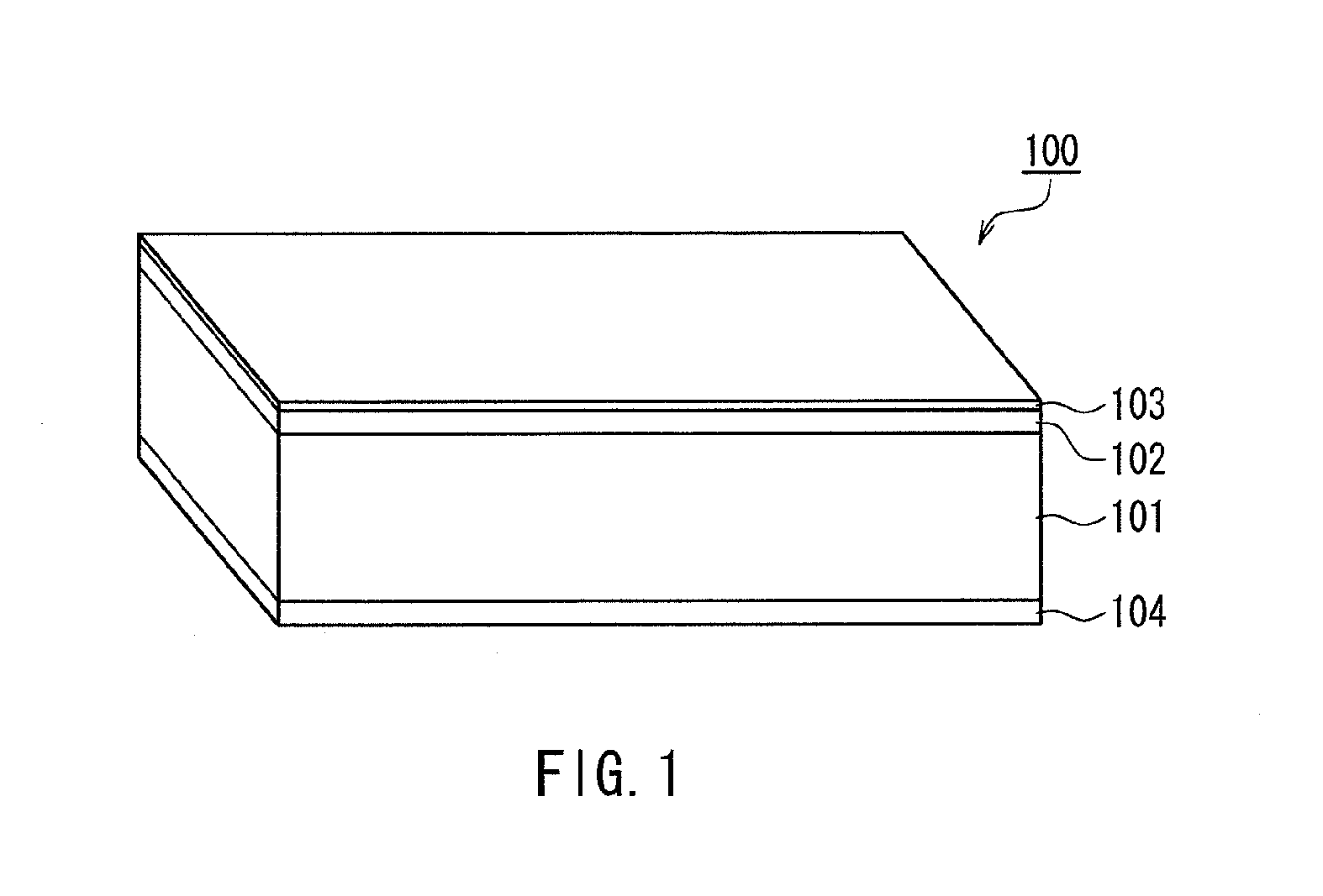
[0013]According to the magnetic recording medium of the present invention, since the surface profile and the lubricant layer thickness of the magnetic recording medium are controlled so as to fall within preferable ranges, it is possible to provide a magnetic recording medium whose magnetic layer has an extremely smooth surface and that has superior recording / reproducing characteristics and transport characteristics.

Problems solved by technology

The smoothed surface of the magnetic tape results in an increase in the contact area between the magnetic head and the magnetic tape, and thus the friction between the head and the tape increases.
Thus, the coefficient of friction increased or sticking tended to occur, resulting in unstable transport, or in extreme cases, the magnetic tape might be cut, or the magnetic head might be damaged.
However, both of the technologies disclosed in JP 2006-127666A and JP 2008-262645A propose the avoidance of sticking of the magnetic tape at the specific positions of the magnetic tape or when the magnetic tape is in the specific states, and do not propose a countermeasure to an increase in the coefficient of friction or sticking at other positions or in other states.

Method used


Image

  • Magnetic recording medium
  • Magnetic recording medium
  • Magnetic recording medium

Examples


example 1

Preparation of Non-Magnetic Paint

[0082]A kneaded product was prepared by kneading non-magnetic paint components (1) listed in Table 1 using a batch-type kneader. The obtained kneaded product and non-magnetic paint components (2) listed in Table 2 were stirred with a stirrer to prepare a mixed solution. The obtained mixed solution was dispersed using a sand mill (residence time: 60 minutes) to prepare a dispersion solution, and afterward, the dispersion solution and non-magnetic paint components (3) listed in Table 3 were stirred with the stirrer, and the resulting solution was filtered through a filter to prepare a non-magnetic paint.

TABLE 1Non-magnetic paint components (1)PartNeedle-like iron oxide (average particle size: 110 nm)68Carbon black (average particle size: 17 nm)20Granular alumina powder (average particle size: 120 nm)12Methyl acid phosphate1Vinyl chloride-hydroxypropyl acrylate copolymer9(—SO3Na group content: 0.7 × 10⁻⁴ equivalent / g)Polyester polyurethane resin5(glass-...

example 2

[0092]After kneading, a part of the magnetic paint components (3) in Table 6 was added into the pressurized batch-type kneader and was diluted to a solid concentration of 50 wt %, and the resulting kneaded and diluted product was directed to a continuous twin-screw kneader. In the continuous twin-screw kneader, the balance of the magnetic paint components (3) was divided into three parts and added separately at three positions in an axial direction of the kneader for stepwise dilution, and thus a slurry was prepared. Otherwise, the same operation as in Example 1 was performed, and thus a magnetic tape for evaluation was produced.

example 3

[0093]A magnetic tape for evaluation was produced in the same manner as in Example 2 except that redispersion was performed by using a collision type dispersing apparatus and passing the magnetic paint obtained by filtering with the filter through a collision chamber twice with an orifice diameter of 0.2 mm and a pressurizing condition of 150 MPa to prepare a magnetic paint, and the calender treatment was performed twice.


PUM


Abstract

A magnetic recording medium of the present invention is a magnetic recording medium including a non-magnetic substrate; a non-magnetic layer that is formed on one of principal surfaces of the non-magnetic substrate and contains a non-magnetic powder, a binder, and a lubricant; and a magnetic layer that is formed on a principal surface of the non-magnetic layer opposite to the non-magnetic substrate and contains a magnetic powder and a binder. The magnetic powder has an average particle size between 10 inn and 35 nm inclusive. The lubricant is migratable to the magnetic layer and forms a lubricant layer on a surface of the magnetic layer when a pressure is applied to the magnetic layer. When spacing of the surface of the magnetic layer before and after washing the lubricant with n-hexane is measured with a TSA (Tape Spacing Analyzer), the value of the spacing after washing is 3 to 10 nm, and the value of the spacing before washing is 1 to 5 nm smaller than the value of the spacing after washing.

Description

BACKGROUND OF THE INVENTION[0001]1. Field of the Invention[0002]The present invention relates to a high-capacity magnetic recording medium, and particularly relates to a magnetic recording medium having superior recording / reproducing characteristics and transport characteristics.[0003]2. Description of the Related Art[0004]Magnetic tapes, which are a type of magnetic recording media, have various applications such as audiotape, videotape, and computer tapes. In particular, in the field of computer data backup tapes, with the increase in the capacity of hard disks to be backed up, tapes having a recording capacity as large as several hundred GB per reel have been put on the market. In the future, in order to support further increases in the capacity of hard disks, it is essential to increase the capacity of such data backup tapes.[0005]With regard to a magnetic tape for use as a data backup tape, the recording wavelength has been shortened with the further increase in the recording c...

Claims


Application Information

Patent Timeline
IPC IPC(8): G11B5/70G11B5/714G11B5/71
CPCG11B5/71G11B5/738G11B5/714G11B5/70615G11B5/733G11B5/7356G11B5/70626G11B5/78
Inventor TANAKA, KENJIFUJITA, MASAOKUSE, SADAMU
Owner FUJIFILM CORP
Learn More