High resolution 3-D holographic camera

a holographic camera, high-resolution technology, applied in the field of cameras, can solve the problems of limited 3-d depth resolution of the holographic scene in practice, the need for illumination scene, and the limitation of being able to record only static scenes, so as to reduce the amount of data used, reduce oscillations, and efficiently generate the complex reference phase

Inactive Publication Date: 2012-02-23
TREX ENTERPRISES CORP
View PDF2 Cites 21 Cited by
  • Summary
  • Abstract
  • Description
  • Claims
  • Application Information

AI Technical Summary

Benefits of technology

[0010]A Reference Spot Holography (RSH) technique, which efficiently produces all speckle data needed to reconstruct the object phase and amplitude, and which can be implemented using a COTS processor chip. RSH projects a sequence of illumination beams, for small spot on target (approximately 0.05-0.1 the width of the object dimension) to provide the data necessary to reconstruct the complex reference beam reconstruction required for holography. A flood illuminated beam of the entire target provides the necessary object spatial frequencies. To provide data necessary for the reconstruction algorithm, the illumination patterns are sequenced in time, stepping through offset phase shifts. The reference spot phase and amplitude are then reconstructed, and reference spot is digitally interfered with the flood illuminated speckle.
[0012]Applicants have developed a sheared beam reconstruction algorithm (SBI algorithm) which efficiently generates the complex reference phase and amplitude from phase gradients. The use of gradient measurements significantly reduces the oscillations in the speckle field, and allows for minimal speckle sampling (2×2 detector pixels / speckle). The SBI algorithm is very fast, and uses built-in noise weighting of gradient measurements. The RSH technique employs SBI reconstructions only on speckle data from a small reference spot illumination region. This effectively reduces the amount of data used by the reconstructor by 2-3 orders of magnitude.
[0013]Applicants use of two colors to obtain surface depth resolution. The frequency of the laser is adjusted by approximately 1 nm in wavelength, producing two distinct measured speckle fields, which are combined to produce depth resolution. Applicants' simulations demonstrate that two colors are sufficient. Applicants scalable detector design uses commercial 1 k×1 k silicon chips, tiled with negligible gap size, to acquire the intensity data over the required sub-field of view. The sensors have up to 600 Hz readout capacity, permitting timely acquisition of all the necessary data. Because Applicants' imaging technique reconstructs object phase and amplitude from intensity measurements (not heterodyne phase detection), the phase aberrations between target and detector do not affect phase of reconstructed amplitude. Applicants' compact beam projection unit consisting of a single holographic element can be produced using existing digital holography fabrication techniques. The phase offsets between successive RSH illuminations is produced by adjusting the position of the single laser beam on the hologram.
[0014]Potential use of compressive holography (CH) augments the RSH approach by increasing the number of voxels that may be inferred from the holographic recording, enabling multi-level reconstruction of features through transparent fabrics, lattice work or translucent (or non-focusing refractive) barriers. The technique allows for extremely deep fields-of-view, supporting simultaneous reconstruction in the Fresnel-Huygens, Fresnel and Fraunhaufer (far field) diffraction regions. CH will be studied as a method to be used in conjunction with RSH.
[0015]Applicants birefringent optical design enables simultaneous reception and segregation of closely-spaced laser wavelengths (nanometer-spacing) into adjacent pixels. This approach employs wide field-of-view high-order waveplate and birefringent grating technologies to enable optimum use of COTS sensor arrays with minimal system complexity. The resulting design reduces the required imager frame rate by 2× and results in a wide-field of view optical design with a minimum of complexity. This is not currently part of Applicants baseline approach, since all the necessary data for RSH can be obtained using commercial COTS sensor elements, so there appears to be no need to separate colors on the detector. But it offers a promising backup, and risk reduction technique, if the sensor read-out fall short of advertised specifications.

Problems solved by technology

A limitation of this method to generating a hologram is that the illuminated scene needs to be static to less than a wavelength of the laser beam during the recording of the hologram.
This can lead to the limitation of only being able to record a static scene, or requiring the use of a short pulse laser in order to freeze the motion of the scene during the recording period.
The 3-D depth resolution of the holographic scene is in practice limited by the stereoscopic parallax resolution estimated by the angular size of the recording medium in relation to the scene.
In general, this depth resolution can only measure gross macroscopic depth profiles, and cannot determine to a high fidelity the very small depth variations of a scene at high spatial resolution.
However, this only works well if the scene has a small change in the depth profile between the two measurements.
Therefore, it requires a significant amount of time to completely scan the target to obtain the full 3-D target profile.
Also, it requires the target to be placed into a profilometer measuring device, and thus is not clandestine method to generate a high resolution 3-D profile.
Heterodyne detection is also corrupted by phase errors arising from optical system aberrations, or aberrations caused by environmental disturbances between the object and detector, such as atmospheric turbulence.

Method used


Image

  • High resolution 3-D holographic camera
  • High resolution 3-D holographic camera
  • High resolution 3-D holographic camera

Examples


Embodiment Construction

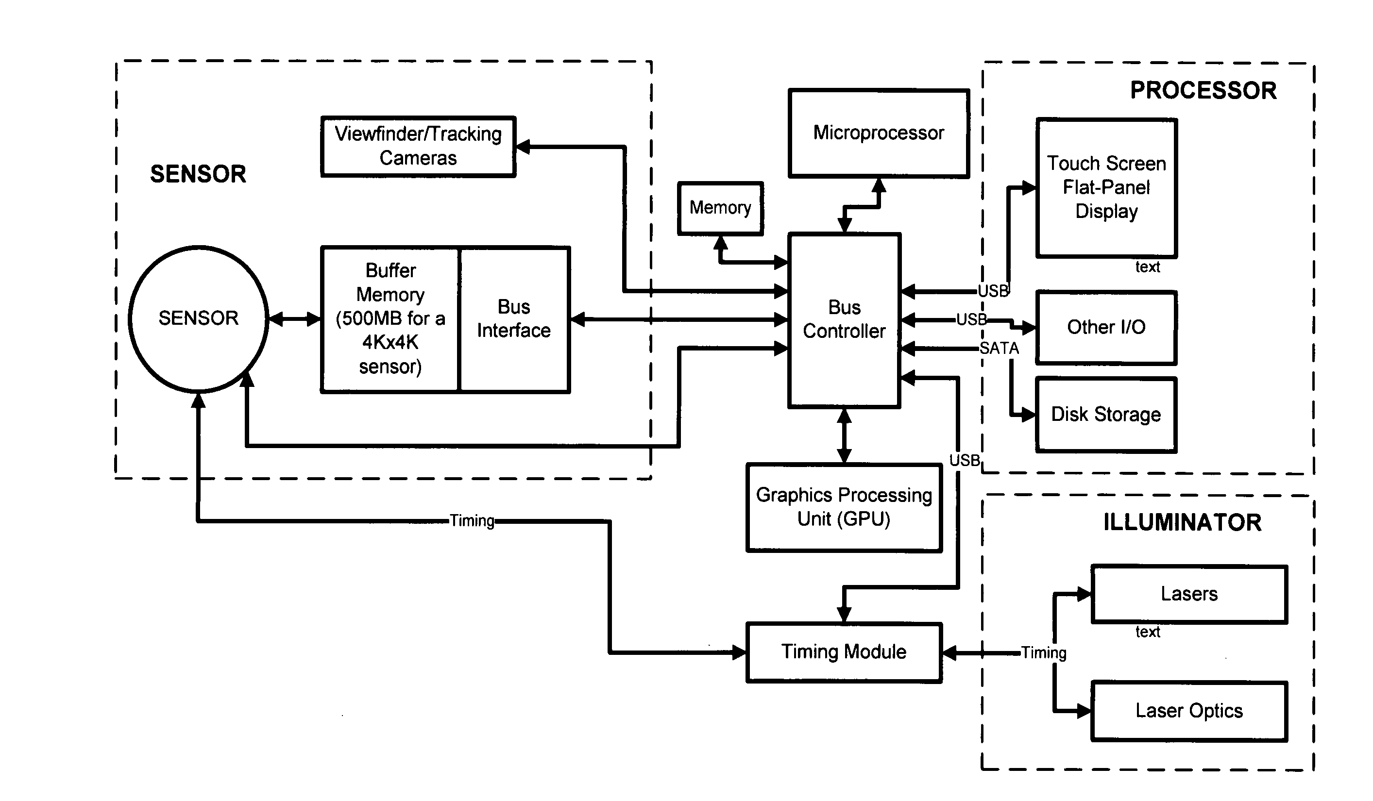
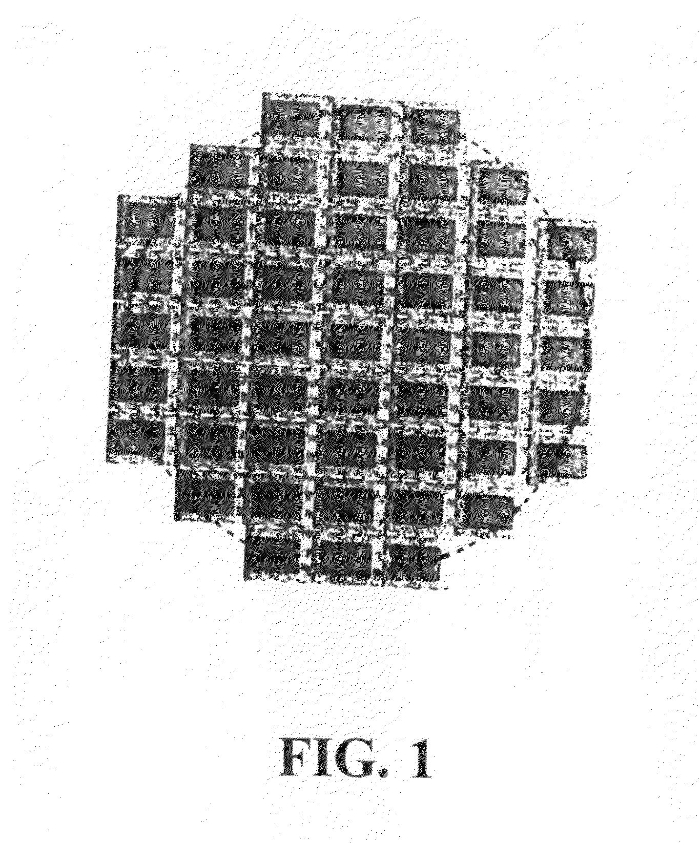
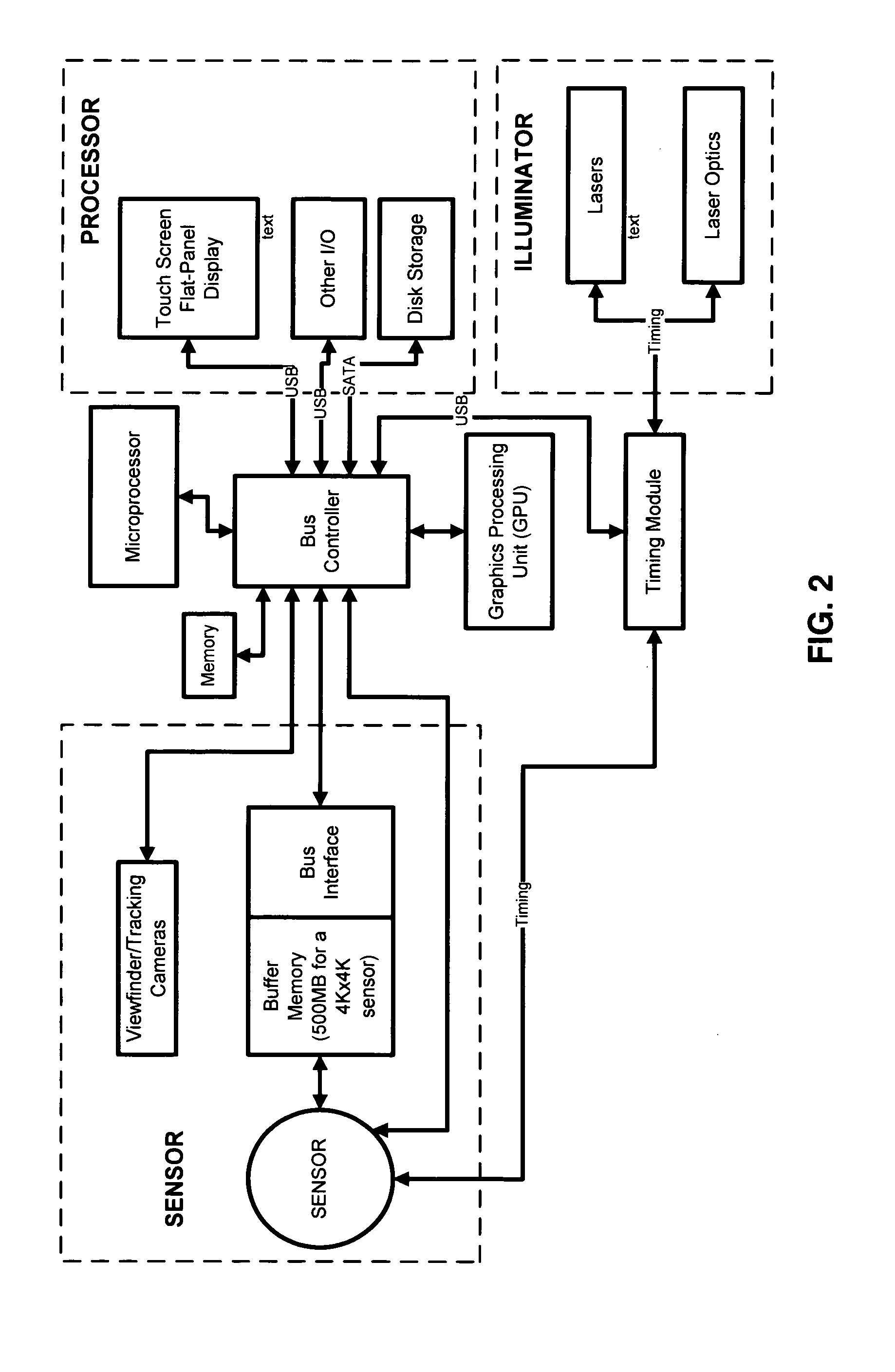
Sensor and Processor

[0022]A preferred embodiment of the present invention includes a tiled sensor. A layout of the sensor is shown in FIG. 1. The sensor is built from commercial chips. The processing electronics is shown in FIG. 2. A major advantage of the approach used by Applicants is that the reconstructor processes phase / amplitude gradients with a special algorithm. The algorithm is an extension of the mathematical approach applied to adaptive optics, using a shearing interferometer wavefront sensor. It is very computationally efficient, does not require phase unwrapping, and its manipulations are performed directly on the desired complex amplitudes.

[0023]Preferred embodiments of the present invention includes three beamlets (formed using a single laser source), separated by shear distances. These beamlets propagate toward the target, overlapping, and interfere on the target, producing fringes. The reflected, optical field directly contains information on the target Fourier spec...


PUM


Abstract

A high resolution 3-D holographic camera. A reference spot on a target is illuminated by three spatially separated beamlets (simultaneously produced from a single laser beam), producing a lateral shear of a wavefront on the target. The camera measures the resulting reflected speckle intensity pattern which are related the gradient of the interfered complex fields. At the same time a flood beam illuminates the entire target and reflected speckle is also recorded by the same camera to provide the necessary object spatial frequencies. The illumination patterns are sequenced in time, stepping through offset phase shifts to provide data necessary to reconstruct an image of the target from the recorded reflected light. The reference spot phase and amplitude are then reconstructed, and the reference spot's complex field is then digitally interfered with the flood illuminated speckle field by use of a special algorithm. In order to obtain a high resolution 3D image of the target, a second measurement is acquired with the laser beam slightly shifted in frequency to second color.

Description

CROSS REFERENCE TO RELATED APPLICATIONS[0001]This application claims the benefit of Provisional Patent Application Ser. No. 61 / 340,086 filed Mar. 11, 2010.FIELD OF THE INVENTION[0002]The present invention relates to cameras and in particular holographic cameras.BACKGROUND OF THE INVENTION[0003]The technique of holography which was originally invented in 1947, and became practically utilized after the invention of the laser in 1960, has widely been used to generate 3-D images. In general, holograms are generated by interfering a laser beam that is scattered from an illuminate scene with a plane wave reference beam. This interference pattern is generally stored on a photographic emulsions or photographic polymers. A limitation of this method to generating a hologram is that the illuminated scene needs to be static to less than a wavelength of the laser beam during the recording of the hologram. This can lead to the limitation of only being able to record a static scene, or requiring t...

Claims


Application Information

Patent Timeline
IPC IPC(8): H04N5/89
CPCG03H1/0443G03H1/0866G01B9/02096G03H2001/0463G01B9/02047G03H2001/0458
Inventor SPIVEY, BRETTSANDLER, DAVIDJOHNSON, PAUL A.FAIRCHILD, PAULCUELLAR, LOUIS
Owner TREX ENTERPRISES CORP
Why Eureka
Try Eureka