
Fan assembly

a technology of fan assembly and rotating blades, which is applied in the direction of machines/engines, liquid fuel engines, positive displacement liquid engines, etc., can solve the problems of uneven or choppy air flow produced by the rotating blades of the fan, uncomfortable for users, and general uneven air flow, so as to achieve uniform outlet width

Active Publication Date: 2010-09-09
DYSON TECH LTD
View PDF102 Cites 128 Cited by
  • Summary
  • Abstract
  • Description
  • Claims
  • Application Information

AI Technical Summary

Benefits of technology

[0008]With this fan assembly an air current can be generated and a cooling effect created without the use of a bladed fan. Advantageously, the use of guide vanes each for directing a portion of the air flow towards the mouth provides a substantially uniform distribution of the air flow through the mouth. By preventing a substantial part of the air flow from being emitted from a relatively small portion of the mouth, a relatively uniform air current can be generated and guided controllably towards a user or into a room, and with little loss in the velocity of the air flow. The air current created by the fan assembly has the benefit of being an air flow with low turbulence and with a more linear air flow profile than that provided by other prior art devices. This can improve the comfort of a user receiving the air flow.
[0011]The direction in which air is emitted from the mouth is preferably substantially at a right angle to the direction in which the air flow passes through at least part of the interior passage. In the preferred embodiment, the air flow passes through at least part of the interior passage in a substantially vertical direction, and the air is emitted from the mouth in a substantially horizontal direction. In view of this, the guide vanes are preferably shaped to change the direction of the air flow by around 90°. The guide vanes are preferably curved so that there is no significant loss in the velocity of the portions of the air flow as they are directed into the mouth. The interior passage is preferably located towards the front of the nozzle, whereas the mouth is preferably located towards the rear of the nozzle and arranged to direct air towards the front of the nozzle and through the opening. Consequently, in the preferred embodiment the mouth is shaped so as substantially to reverse the flow direction of each portion of the air flow as it passes from the interior passage to an outlet of the mouth. The mouth is preferably substantially U-shaped in cross-section, and preferably narrows towards the outlet thereof
[0014]The guide vanes preferably engage the internal surface of the outer casing section of the nozzle so as to urge apart the overlapping portions of the inner casing section and the outer casing section of the nozzle. This can enable a substantially uniform outlet width to be achieved about the opening. The uniformity of the outlet width results in a relatively smooth, substantially even output of air from the nozzle. Depending on the spacing between adjacent guide vanes, one or more additional spacers may be located between adjacent guide vanes, preferably also integral with the inner casing section of the nozzle, to maintain a regular spacing between the overlapping portions of the inner casing section and the outer casing section of the nozzle.
[0017]In the preferred fan assembly the device for creating an air flow through the nozzle comprises an impeller driven by a motor. This can provide a fan assembly with efficient air flow generation. The device for creating an air flow preferably comprises a DC brushless motor and a mixed flow impeller. This can avoid frictional losses and carbon debris from the brushes used in a traditional brushed motor. Reducing carbon debris and emissions is advantageous in a clean or pollutant sensitive environment such as a hospital or around those with allergies. While induction motors, which are generally used in bladed fans, also have no brushes, a DC brushless motor can provide a much wider range of operating speeds than an induction motor.
[0023]Preferably, the nozzle comprises a Coanda surface located adjacent the mouth and over which the mouth is arranged to direct the air flow. In a preferred embodiment the nozzle comprises a diffuser located downstream of the Coanda surface. The diffuser directs the air flow emitted towards a user's location while maintaining a smooth, even output, generating a suitable cooling effect without the user feeling a ‘choppy’ flow.

Problems solved by technology

A disadvantage of this type of arrangement is that the air flow produced by the rotating blades of the fan is generally not uniform.
These variations result in the generation of an uneven or ‘choppy’ air flow which can be felt as a series of pulses of air and which can be uncomfortable for a user.
It is undesirable for parts of the appliance to project outwardly, or for a user to be able to touch any moving parts, such as the blades.
Many fans tend to have safety features such as a cage or shroud around the blades to prevent injury from the moving parts of the fan, but such caged parts can be difficult to clean.

Method used


Image

  • Fan assembly
  • Fan assembly
  • Fan assembly

Examples


Embodiment Construction

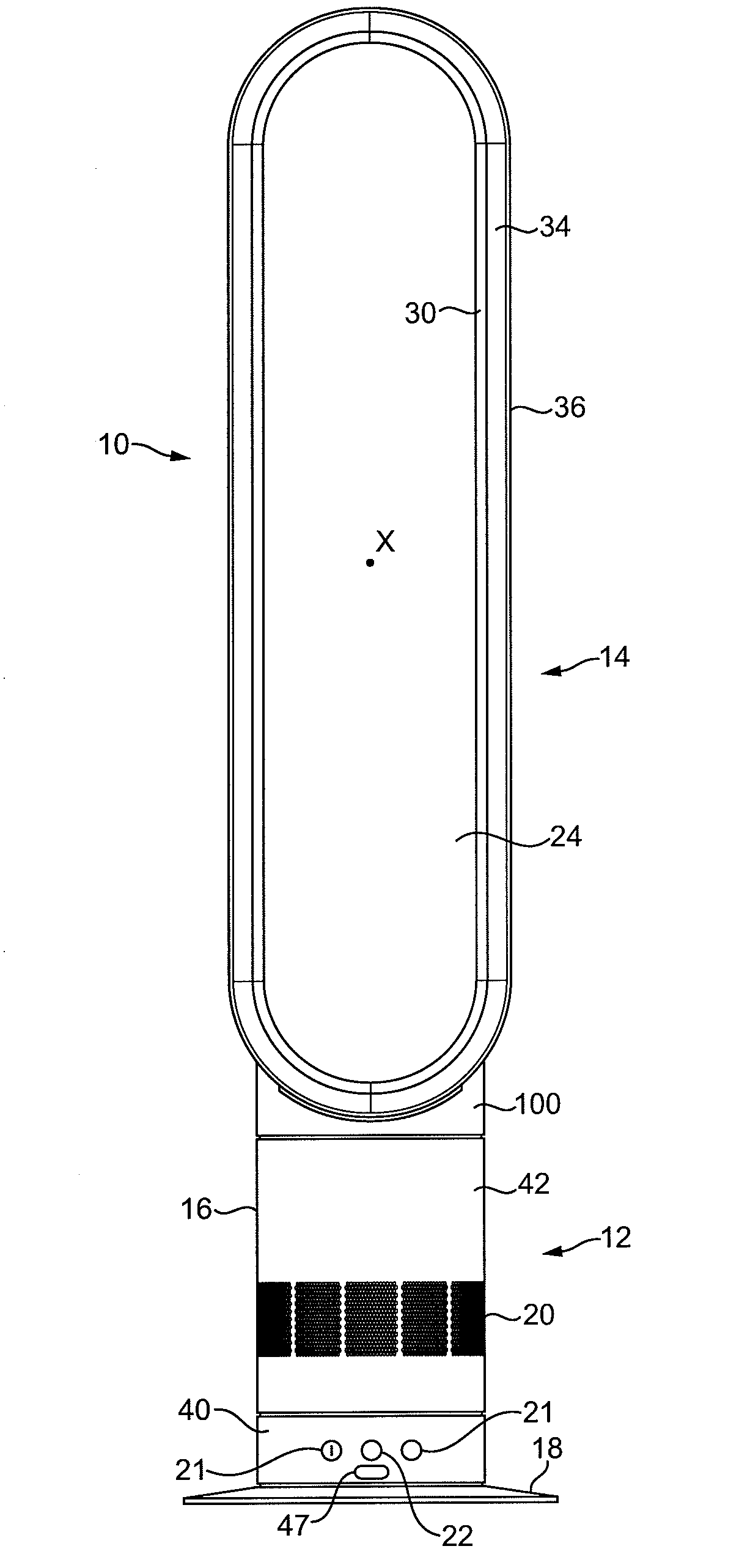
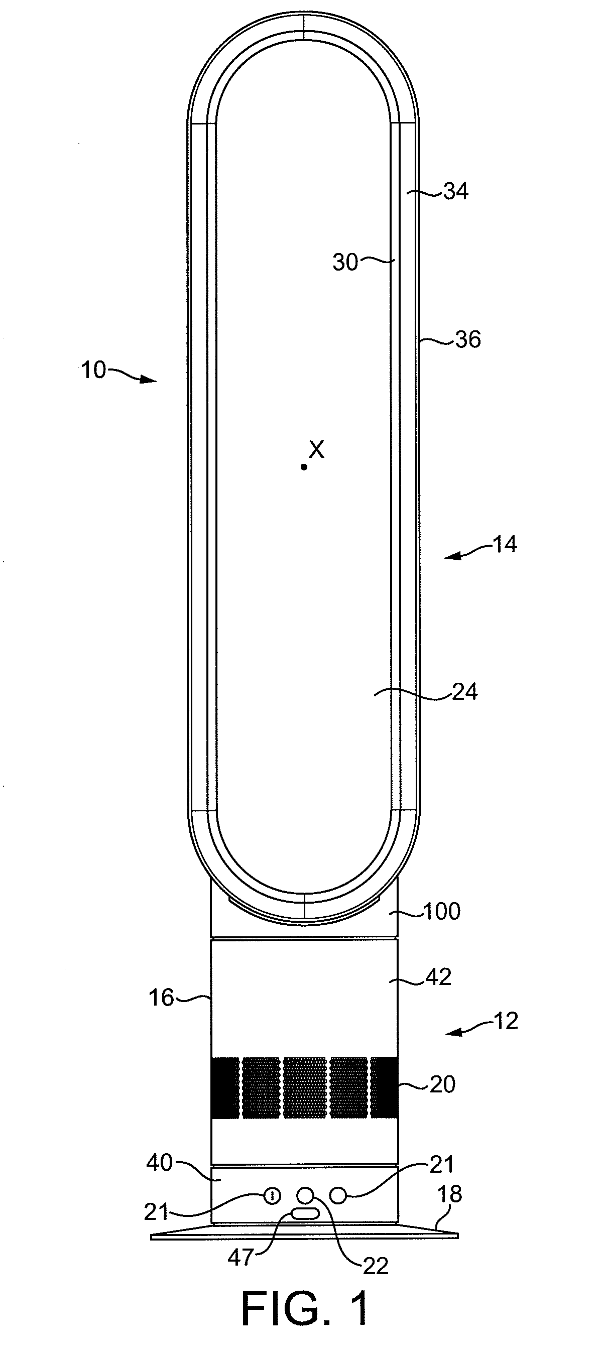
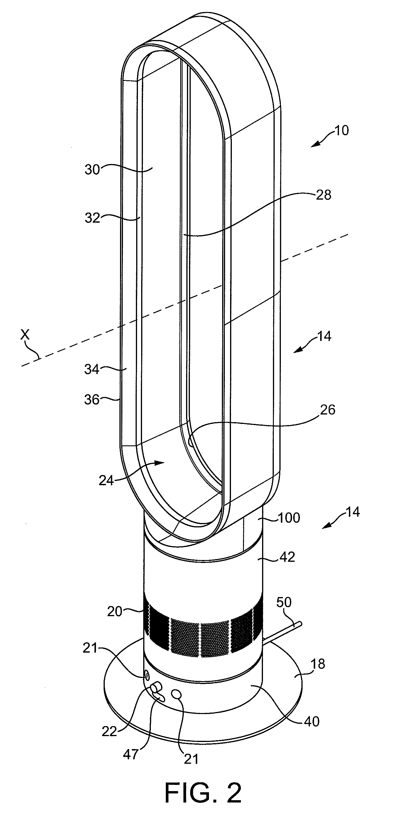
[0040]FIGS. 1 and 2 illustrate an embodiment of a bladeless fan assembly. In this embodiment, the bladeless fan assembly is in the form of a domestic, portable tower fan 10 comprising a base 12 and an air outlet in the form of a nozzle 14 mounted on and supported by the base 12. The base 12 comprises a substantially cylindrical outer casing 16 mounted optionally on a disc-shaped base plate 18. The outer casing 16 comprises a plurality of air inlets 20 in the form of apertures formed in the outer casing 16 and through which a primary air flow is drawn into the base 12 from the external environment. The base 12 further comprises a plurality of user-operable buttons 21 and a user-operable dial 22 for controlling the operation of the fan 10. In this embodiment the base 12 has a height in the range from 100 to 300 mm, and the outer casing 16 has a diameter in the range from 100 to 200 mm.

[0041]The nozzle 14 has an elongate, annular shape and defines a central elongate opening 24. The noz...


PUM


Abstract

A bladeless fan assembly includes a nozzle mounted on a base housing a motor and an impeller driven by the motor for creating an air flow. The nozzle includes an interior passage for receiving the air flow, a mouth for emitting the air flow, and a plurality of stationary guide vanes located within the interior passage and each for directing a portion of the air flow towards the mouth. The nozzle defines an opening through which air from outside the fan assembly is drawn by the air flow emitted from the mouth.

Description

REFERENCE TO RELATED APPLICATIONS[0001]This application claims the priority of United Kingdom Application No. 0903680.7 filed 4 Mar. 2009, the entire contents of which are incorporated herein by reference.FIELD OF THE INVENTION[0002]The present invention relates to a fan assembly. In a preferred embodiment, the present invention relates to a domestic fan, such as a tower fan, for creating an air current in a room, office or other domestic environment.BACKGROUND OF THE INVENTION[0003]A conventional domestic fan typically includes a set of blades or vanes mounted for rotation about an axis, and drive apparatus for rotating the set of blades to generate an air flow. The movement and circulation of the air flow creates a ‘wind chill’ or breeze and, as a result, the user experiences a cooling effect as heat is dissipated through convection and evaporation.[0004]Such fans are available in a variety of sizes and shapes. For example, a ceiling fan can be at least 1 m in diameter, and is usu...

Claims


Application Information

Patent Timeline
Patent Type & Authority Applications(United States)
IPC IPC(8): F03B11/02
CPCF04D25/08F04F5/46F04F5/16F04D29/444F04F5/20F04D29/44
Inventor HELPS, DANIEL FRANCIS
Owner DYSON TECH LTD
Learn More