
Wiring circuit board

a wiring circuit and circuit technology, applied in the direction of printed circuit manufacturing, printed circuit components, integrated arm assemblies, etc., can solve the problems of reducing the durability of the wiring, and brittleness of the circuit wiring having a higher hardness, so as to improve the durability and tensile resistance of the respective metal layer, the effect of less brittleness

Inactive Publication Date: 2012-02-09
NITTO DENKO CORP
View PDF10 Cites 9 Cited by
  • Summary
  • Abstract
  • Description
  • Claims
  • Application Information

AI Technical Summary

Benefits of technology

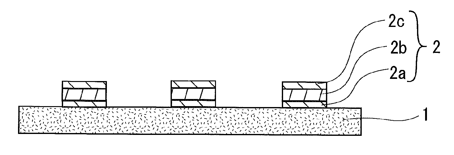
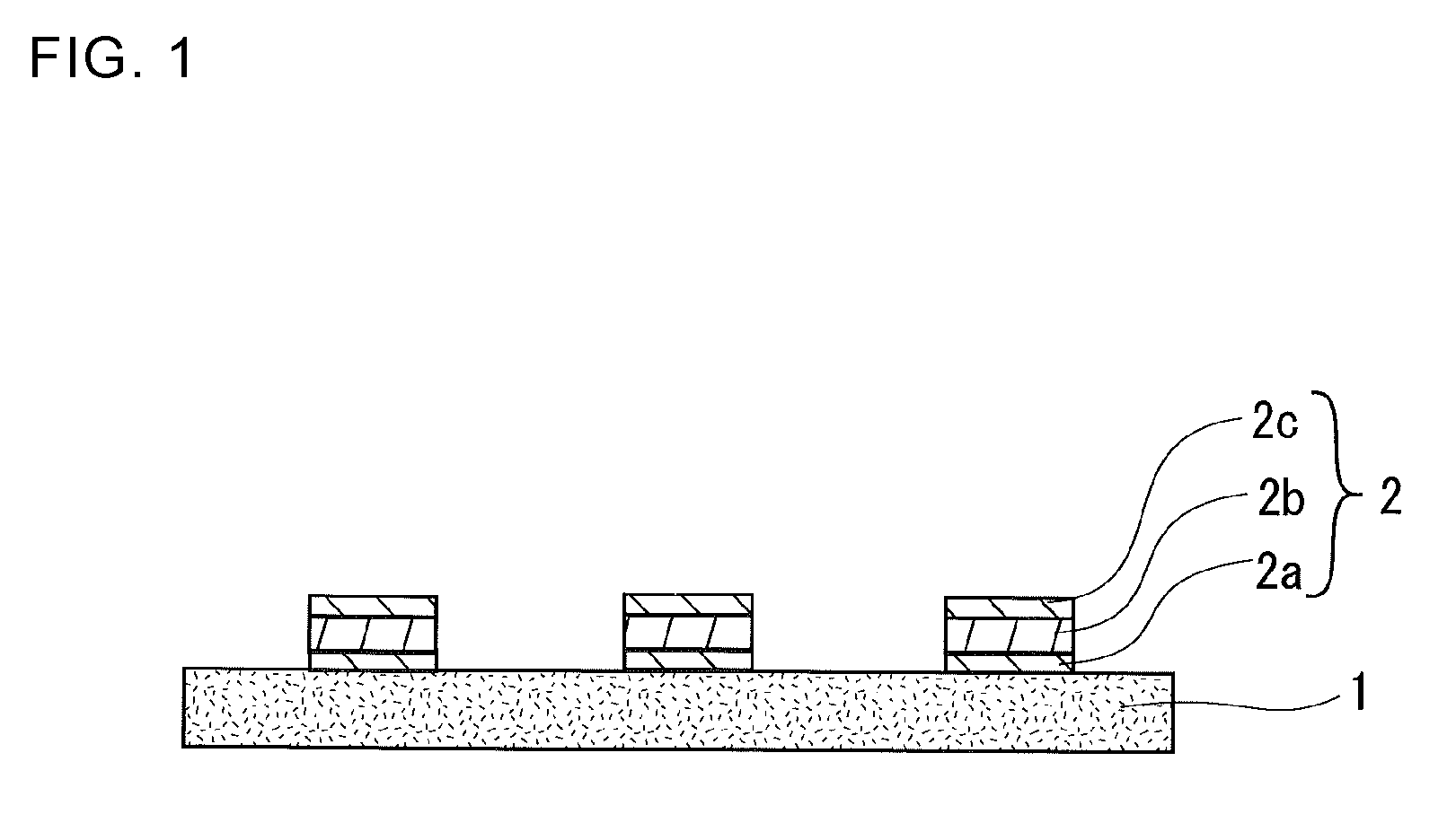
[0013]Where the circuit wiring of the wiring circuit board has the layered structure including the at least three copper-based metal layers, and the lowermost and uppermost copper-based metal layers each have a tensile resistance of 100 to 400 MPa at the ordinary temperature, and the intermediate copper-based metal layer present between the lowermost and uppermost layers has a tensile resistance of 700 to 1500 MPa at the ordinary temperature, the higher hardness of the intermediate copper-based metal layer present between the lowermost and uppermost layers suppresses the softening phenomenon of the circuit wiring which may otherwise occur due to heat over time to thereby improve the durability, and the lower hardness of the lowermost and uppermost layers present on opposite sides of this intermediate layer suppresses the cracking when the board is bent.
[0019]Where the intermediate layer present between the lowermost and uppermost layers comprises copper as a major component and 100 to 3000 ppm of bismuth, the circuit wiring is substantially free from the softening phenomenon which may otherwise occur due to heat over time, and hence has higher tensile resistance for a longer period of time.

Problems solved by technology

However, the wirings formed by the plating through the aforementioned additive method are excellent in durability immediately after the plating, but suffer from a softening phenomenon called “self-anneal” occurring due to environmental heat over time.
The softening phenomenon is liable to reduce the durability of the wirings when the electronic components are mounted on the board.
However, the circuit wirings having higher hardness are more brittle, suffering from cracking when the wiring circuit board is bent.

Method used


Image

  • Wiring circuit board
  • Wiring circuit board

Examples


examples

Electrolytic Solution A

[0038]An electrolytic solution A was prepared by blending 70 g / l of copper sulfate (CuSO45.H2O) (available from JX Nikko Mining & Metal Corporation), 180 g / l of sulfuric acid (H2SO4) (available from Wako Pure Chemical Industries Limited), 40 mg / l of chlorine (available from Wako Pure Chemical Industries Limited), and 3 ml / l of an organic additive (CC-1220 available from Electroplating Engineers of Japan Limited).

Electrolytic Solution B

[0039]An electrolytic solution B was prepared by blending 70 g / l of copper sulfate (CuSO4.5H2O) (available from JX Nikko Mining & Metal Corporation), 180 g / l of sulfuric acid (H2SO4) (available from Wako Pure Chemical Industries Limited), 40 mg / l of chlorine (available from Wako Pure Chemical Industries Limited), 3 ml / l of an organic additive (CC-1220 available from Electroplating Engineers of Japan Limited), and 2.0 g / l of bismuth sulfate (Bi2(SO4)3) (available from Wako Pure Chemical Industries Limited).

Electrolytic Solution C

[...


PUM

PropertyMeasurementUnit
temperatureaaaaaaaaaa
thicknessaaaaaaaaaa

Abstract

A wiring circuit board is provided, in which a circuit wiring is substantially free from a softening phenomenon which may otherwise occur due to heat over time, and is highly durable, less brittle and substantially free from cracking. The wiring circuit board includes a substrate comprising an insulative layer, and a circuit wiring provided on the insulative layer of the substrate. The circuit wiring has a layered structure including at least three copper-based metal layers. A lowermost one and an uppermost one of the copper-based metal layers each have a tensile resistance of 100 to 400 MPa at an ordinary temperature, and an intermediate copper-based metal layer present between the lowermost layer and the uppermost layer has a tensile resistance of 700 to 1500 MPa at the ordinary temperature.

Description

BACKGROUND OF THE INVENTION[0001]1. Field of the Invention[0002]The present invention relates to a wiring circuit board and, more specifically, to a wiring circuit board which is useful as a flexible circuit board and the like.[0003]2. Description of the Related Art[0004]Wiring circuit boards, which generally include an insulative film such as of a polyimide and thin film electric wirings formed in an electrically conductive circuit pattern on the insulative film, are flexible, and are widely employed as suspension boards for read / write heads of hard disks, circuit boards for liquid crystal display devices, and the like. In recent years, products are increasingly required to be lighter in weight and smaller in thickness and overall size, and to record information at higher density.[0005]Correspondingly, the wiring circuit boards are required to include a greater number of wirings formed in a limited area thereof. That is, there is a demand for formation of a finer wiring pattern.[00...

Claims


Application Information

Patent Timeline
Patent Type & Authority Applications(United States)
IPC IPC(8): H05K1/02
CPCC25D5/10G11B5/484H05K1/0393H05K2201/0355H05K3/108H05K2201/0338H05K1/09C25D5/617C25D1/04H05K3/18
Inventor EBE, HIROFUMI
Owner NITTO DENKO CORP
Learn More