
Sawing wire with abrasive particles partly embedded in a metal wire and partly held by an organic binder

Inactive Publication Date: 2012-01-26
BEKAERT BINJIANG STEEL CORD CO LTD
View PDF20 Cites 19 Cited by
  • Summary
  • Abstract
  • Description
  • Claims
  • Application Information

AI Technical Summary

Benefits of technology

[0017]To increase the useful lifetime of the sawing wire by better holding the abrasive particles.
[0079]When producing the fixed abrasive sawing wire by means of indentation of particles, the particles can be applied on the metallic wire without any organic binder followed by coating and complete cure. Alternatively the particles can be applied after the organic binder has been put on. In the latter case it is preferred to first coat the metallic wire with an organic binder layer followed by a slight curing, followed by indentation and finishing with a complete cure of the coating in order to prevent smudging of the indentation wheels during indentation.

Problems solved by technology

‘Kerf loss’ is the material loss due to the abrading away of the (expensive) material.
However, it is not the wire itself that saws, but an abrasive added to the process.
Also the slurry degrades as the abrasive particles lose their sharpness.
In addition the slurry gets loaded with the swarf of the material and the debris of the wire and must be renewed regularly which brings environmental issues with it.
However, the process is gentle to the material and therefore liked very much in the semiconductor industry where subsurface damage is an important issue.
However, the use of nickel baths has raised health concerns as metallic nickel and in particular nickel salts are known to be carcinogenic (reference is made to the 30th amendment of EC Directive 67 / 548 / EEC).
However, brazing results in a considerable thermal loading of the wire which results in a loss of tensile strength of the wire (unless very particular metallic wires are used as a substrate).
Although this results in a cost effective and efficient way of fixing the abrasive on the—usually metallic—wire the fixation is not that strong and the resulting cutting speeds are lower than those obtained in the routes mentioned above.
Drawbacks are that the method does not allow to produce fixed abrasive sawing wires of an appreciable length (above 100 meters), the tensile strength of the resulting wire is relatively low (say below 1800 N / mm2) and the resulting wires are too thick (1 mm).
It adds considerable length to the overall length of the line and the ancillaries (pumping, tubing, vessels) and safety precautions make it an expensive operation.

Method used


Image

  • Sawing wire with abrasive particles partly embedded in a metal wire and partly held by an organic binder
  • Sawing wire with abrasive particles partly embedded in a metal wire and partly held by an organic binder
  • Sawing wire with abrasive particles partly embedded in a metal wire and partly held by an organic binder

Examples


Embodiment Construction

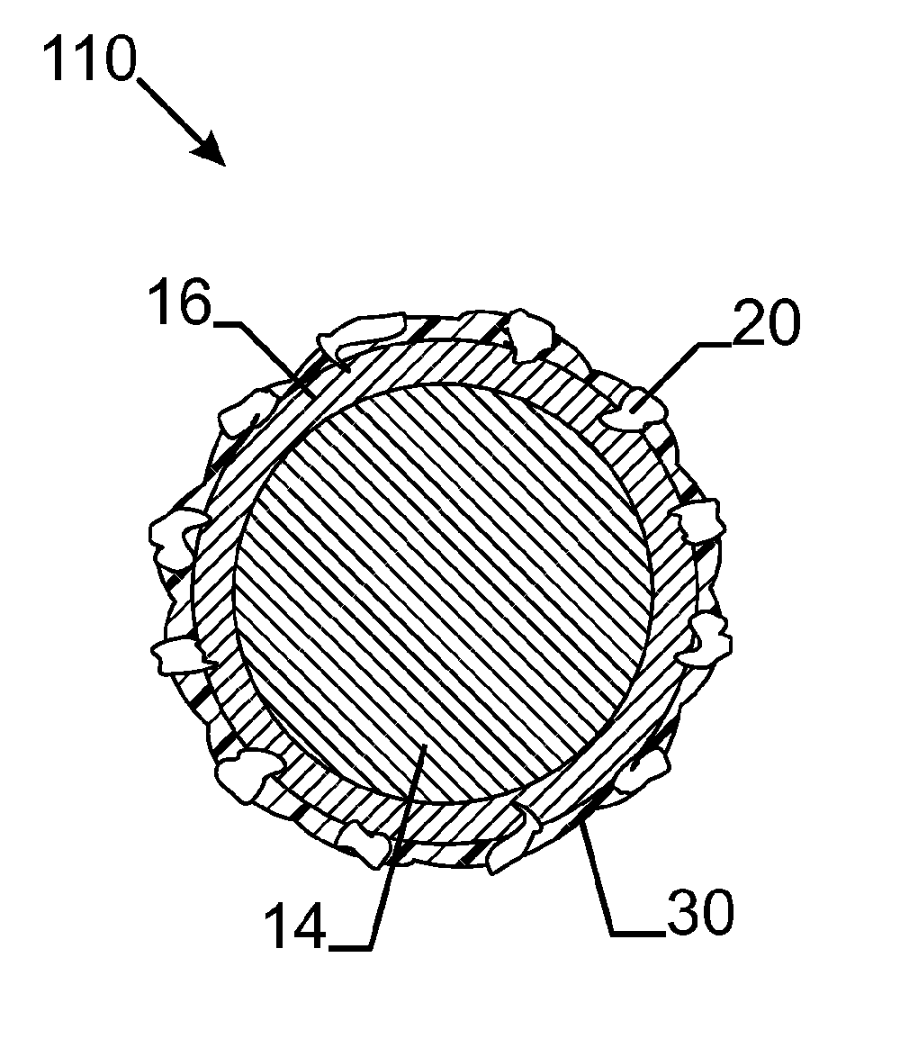
[0086]FIG. 1a shows the invention in its most generic form (first embodiment). A fixed abrasive sawing wire 100 comprises a metallic wire 12 and an organic binder layer 30. Abrasive particles 20 are fixed to the metallic wire 12 by means of the organic layer 30. Characteristic about the wire is that the abrasive particles are also partly embedded in the metallic wire. FIG. 1b shows a second preferred embodiment wherein the metallic wire comprises a core 14 and a sheath 16 and wherein the abrasive particles are partly embedded in the sheath 16 and bound to the wire by the organic binder layer 30. The particles are embedded at the most one third of their median size in the sheath layer, the remainder being bound in the organic binder layer.

[0087]FIG. 1c shows a third preferred embodiment wherein the interface between the sheath 16 and the core 14 shows a certain roughness. Here the particles have at least two thirds of their median size in the sheath. FIG. 1d shows a fourth preferred ...


PUM

PropertyMeasurementUnit
Adhesion strengthaaaaaaaaaa
Abrasiveaaaaaaaaaa
Metallic bondaaaaaaaaaa

Abstract

A sawing wire (100,110,120,130) with abrasive particles (20) is presented wherein the particles (20) are partly embedded in said a metallic core (14) and partly in said an organic binder layer (30). The advantage of the wire (100,110,120,130) is that the application of a metallic binder layer (30) can be avoided. Metallic binder layers add to the cost of a fixed abrasive sawing wire and in many cases pose health and safety problems which can be avoided by the use of an organic binder layer. Moreover the advantages of a good fixture of the abrasive particles in the metallic wire are maintained. Different embodiments are presented with different degrees of embedment into the metal wire.

Description

TECHNICAL FIELD[0001]The invention relates to a metallic wire for sawing hard and brittle materials that has abrasive particles affixed to its outer surface. The particles are fixed to the wire by embedding them partly into the metal and partly in a polymeric binder layer. The fixed abrasive sawing wire is particularly suited to cut expensive materials where a low kerf loss and a limited surface or subsurface damage is desirable.BACKGROUND ART[0002]Wire saws have gradually replaced the internal diameter rotating sawing blades for cutting expensive materials that are hard and brittle. Examples of such materials are quartz (for e.g. quartz oscillators or mask blancs), silicon (for e.g. integrated circuit wafers or solar cells), germanium (e.g. as substrate for gallium arsenide solar cells), gallium arsenide (for high frequency circuitry), silicon carbide or sapphire (e.g. for blue led or blue led substrates), rare earth magnetic alloys (e.g. for recording heads) and the like. One of t...

Claims


Application Information

Patent Timeline
IPC IPC(8): B26D1/547B28D1/12
CPCB23D61/185B28D5/042B24B27/0633Y10T83/9292
Inventor LANGE, MARTINVANEECKE, JANLAMEIRE, REBECCA
Owner BEKAERT BINJIANG STEEL CORD CO LTD
Learn More