Eureka AIR delivers breakthrough ideas for toughest innovation challenges, trusted by R&D personnel around the world.

Method of manufacturing lens casting mold

Inactive Publication Date: 2011-12-15
HOYA CORP
View PDF0 Cites 13 Cited by
  • Summary
  • Abstract
  • Description
  • Claims
  • Application Information

AI Technical Summary

Benefits of technology

[0027]The present invention permits the manufacturing with high production efficiency of l

Problems solved by technology

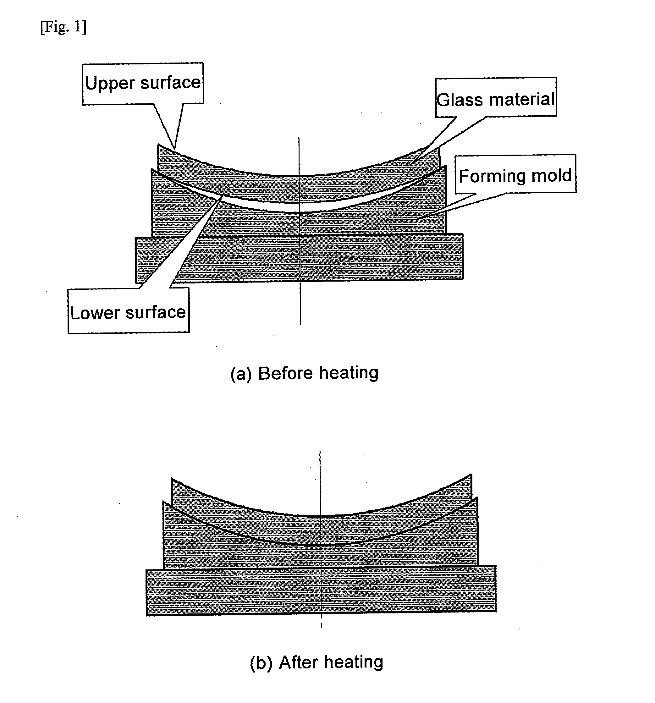
However, in a continuous heating furnace, the amount of change in various parts of the surface of the object being heated tends to be nonuniform due to the presence of the temperature distribution in the conveyance direction, as stated above.
When the amount of deformation varies with the position of the glass material in this manner, the timing at which the lower surface of the glass material contacts the forming surface of the mold varies greatly with position, producing astigmatism that is undesirable in eyeglass correction and sometimes compromising the sensation created by wearing the eyeglass because the deviation from the design value is asymmetric.
However, when the glass material is rapidly rotated during softening in the course of molding a glass material by the hot sag forming method, there is a risk of reducing molding precision.

Method used


Image

  • Method of manufacturing lens casting mold
  • Method of manufacturing lens casting mold
  • Method of manufacturing lens casting mold

Examples


example 1

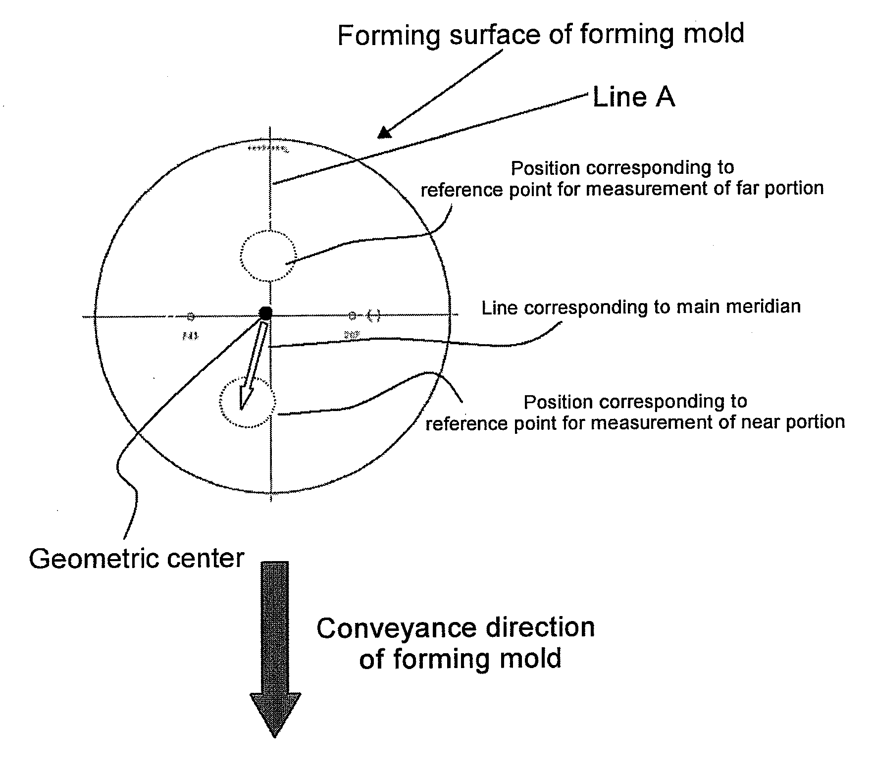
[0143]Two double-spherical-surface glass preforms of uniform thickness in the normal direction were positioned on the forming surfaces of forming molds having forming surfaces corresponding to a progressive dioptric power lens, both surfaces of which are aspherical, having a compound surface comprising a toric surface and a progressive surface with a far portion and a near portion. Next, the forming molds on which the preforms had been positioned were introduced into an electric furnace such that the direction of maximum average curvature from the geometric center of the forming surface toward the rim portion was aligned with the conveyance direction, and conveyed through the interior of the furnace. In this state, the angle between a straight line corresponding to the axis of astigmatism of the toric surface of the forming surface of the forming molds and the conveyance direction was 90°. Temperature control was effected within the electric furnace in the same manner as set forth a...


PUM

PropertyMeasurementUnit
Angleaaaaaaaaaa
Frequencyaaaaaaaaaa
Temperatureaaaaaaaaaa

Abstract

The present invention relates to a method of manufacturing a lens casting mold by introducing a forming mold, with a forming surface on which is positioned a glass material being formed, into a continuous heating furnace and conducting thermal treatment while conveying the forming mold to form an upper surface of the glass material being formed into a shape of a molding surface for forming a surface comprising a progressive surface. The method of manufacturing a lens casting mold of the present invention comprises controlling a temperature of the continuous heating furnace so that the continuous heating furnace comprises a temperature rising region having a temperature distribution such that the temperature rises in a conveyance direction of the forming mold; utilizing a forming mold having a curvature distribution on the forming surface as the forming mold; and conveying the forming mold in the temperature rising region so that a portion with the largest curvature on the forming surface is comprised in a portion on a side of the conveyance direction as divided in two by an imaginary line, the imaginary line running orthogonally to the conveyance direction of the forming mold and passing through a geometric center of the forming surface.

Description

CROSS-REFERENCE TO RELATED APPLICATIONS[0001]This application claims the benefit of priority to Japanese Patent Application Nos. 2008-020860, 2008-020875, and 2008-020921 filed on Jan. 31, 2008, which are expressly incorporated herein by reference in their entirety.TECHNICAL FIELD[0002]The present invention relates to a method of manufacturing a lens casting mold by hot sag forming method.TECHNICAL BACKGROUND[0003]Methods of forming glass molds for eyeglass lenses include employing mechanical grinding and polishing methods, mechanical grinding methods, and electrical processing methods such as electrical discharge processing to produce a heat-resistant base mold, bringing this base mold into contact with a glass blank softened by heating to transfer the surface shape of the base mold, employing a grinding program for each surface shape to be obtained, and forming a base mold having a corresponding surface shape.[0004]In recent years, the demand has increased for multifocal eyeglass ...

Claims


Application Information

Patent Timeline
IPC IPC(8): B29C33/38
CPCB29L2011/0016C03B29/06C03B23/0026B29L2031/757
Inventor TAGUCHI, NORIAKITAKIZAWA, SHIGERUSHIMIZU, HIDETAKA
Owner HOYA CORP
Why Eureka
Eureka Blog
Learn More