
Insulating varnish and insulated wire formed by using the same

a technology of insulating varnish and insulated wire, which is applied in the direction of insulated conductors, cables, conductors, etc., can solve the problems of increasing the relative dielectric constant, aggregation of fine particles, and reducing the partial discharge inception voltage of the insulated wire, so as to improve the compatibility with the resin component (x) and the compatibility, and achieve high partial discharge inception voltage. , the effect of improving the compatibility

Inactive Publication Date: 2011-12-01
HITACHI CABLE
View PDF4 Cites 29 Cited by
  • Summary
  • Abstract
  • Description
  • Claims
  • Application Information

AI Technical Summary

Benefits of technology

[0011]In reply to these requirements, an insulating varnish may be proposed that the organosol disclosed in JP-A-2001-307557 and JP-A-2006-299204 is dispersed in the polyamide-imide resin insulating varnish disclosed in JP-A-2009-161683. However, if the organosol is simply combined with the polyamide-imide resin insulating varnish, the low compatibility between the organosol and the polyamide-imide resin insulating varnish, may cause an increase in relative dielectric constant, aggregation of fine inorganic particles, or the like. Thereby, the partial discharge inception voltage of an insulated wire may decrease, and the insulating coating may deteriorate easily. Namely, the property of the insulating coating rather deteriorates.
[0033]According to one embodiment of the invention, an insulating varnish is prepared such that an isocyanate component (Y), which is reacted with the resin component (X) in a synthesis reaction (the second synthesis reaction) in order to obtain a polyamide-imide resin varnish contained in the insulating varnish, necessarily includes a diisocyanate (Y1) which includes a bent structure in a molecule thereof. The diisocyanate (Y1) including the bent structure in the molecule comprises preferably a diisocyanate including a divalent aromatic group having two aromatic rings, in order to improve the compatibility with the resin component (X) and the compatibility between the polyamide-imide resin obtained finally and the organosol.
[0034]Thus, the insulating varnish can form an insulating coating that has a high partial discharge inception voltage and is less subject to a dielectric breakdown even if an inverter surge voltage occurs, and an insulated wire can be formed by using the insulating varnish.

Problems solved by technology

Thus, the high inverter surge voltage may cause a partial discharge in the insulated wire to have a dielectric breakdown.
However, if the organosol is simply combined with the polyamide-imide resin insulating varnish, the low compatibility between the organosol and the polyamide-imide resin insulating varnish, may cause an increase in relative dielectric constant, aggregation of fine inorganic particles, or the like.
Thereby, the partial discharge inception voltage of an insulated wire may decrease, and the insulating coating may deteriorate easily.
Namely, the property of the insulating coating rather deteriorates.

Method used


Image

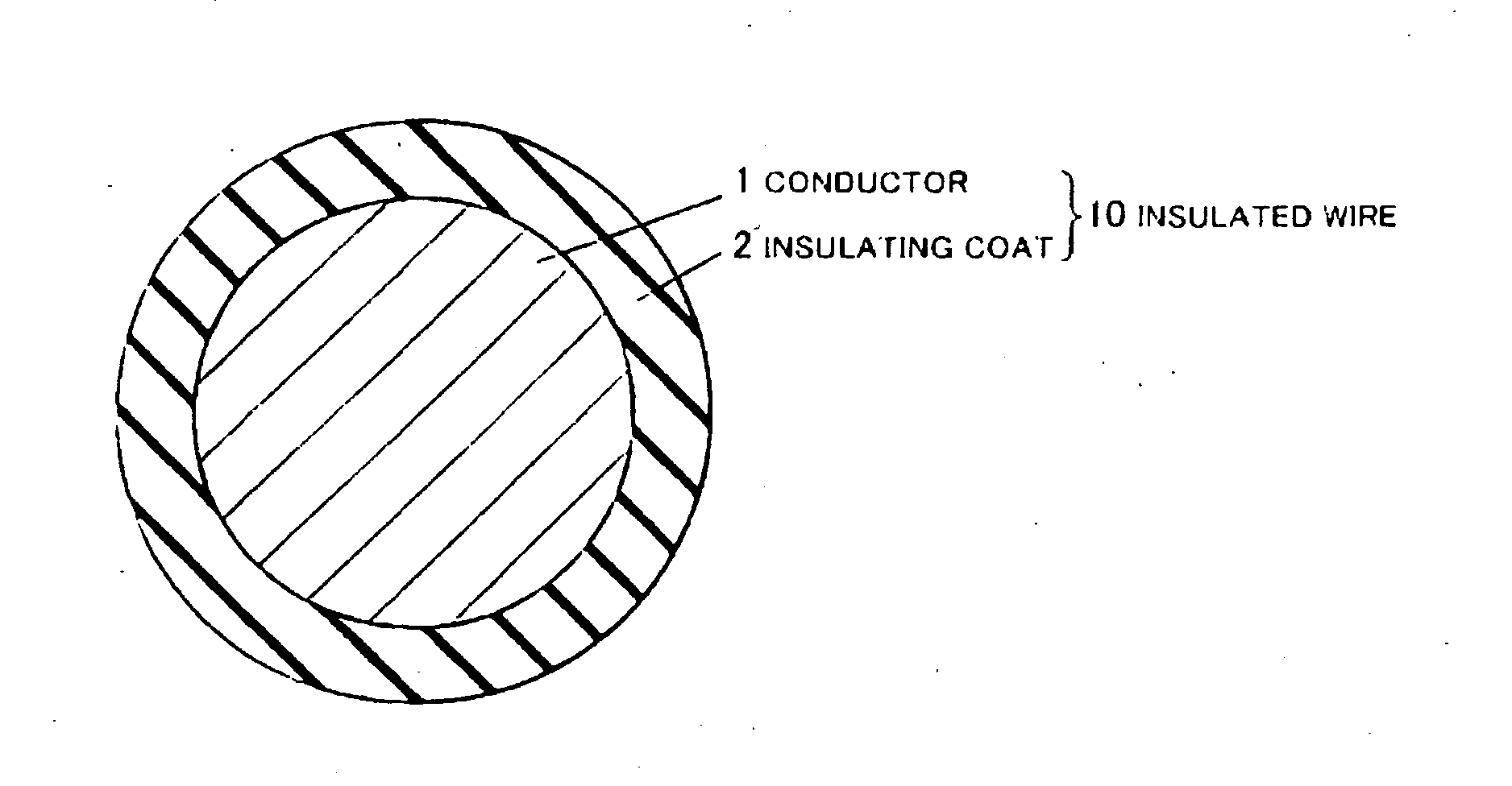
  • Insulating varnish and insulated wire formed by using the same
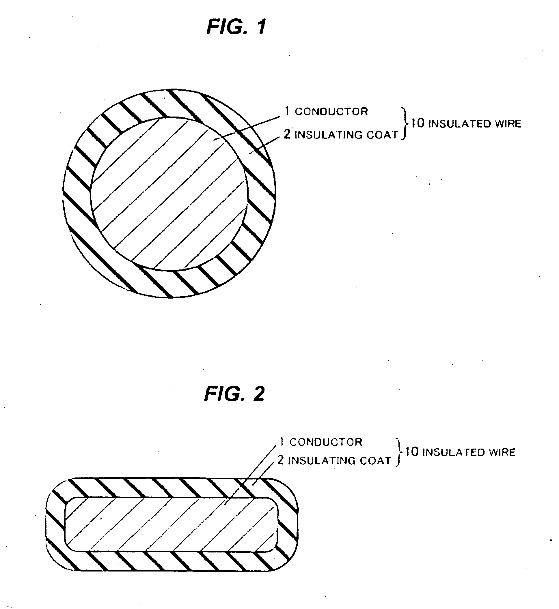
  • Insulating varnish and insulated wire formed by using the same
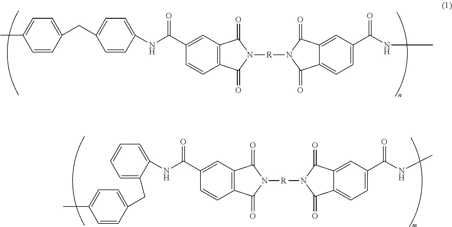
  • Insulating varnish and insulated wire formed by using the same

Examples


example 1

[0083]Silica particle sol containing 10 parts by mass of silica component was dispersed into the polyamide-imide resin varnish (A) relative to 100 parts by mass of the resin part of the polyamide-imide resin vanish (A) while the polyamide-imide resin varnish (A) was being stirred, insulating varnish was thereby obtained. Here, dispersion medium and dispersion particles of the silica particle sol were respectively gamma-butyrolactone and silica particles having an average diameter of 12 nm. Then, applying and baking of the insulating varnish on a copper wire having diameter of 0.80 mm were repeated so that an insulating coating was formed in thickness of 0.045 mm. As a result, an insulated wire in example 1 was obtained.

example 2

[0084]Silica particle sol containing 90 parts by mass of silica component was dispersed into the polyamide-imide resin varnish (A) containing 100 parts by mass of the resin component (X) while the polyamide-imide resin varnish (A) was being stirred, insulating varnish was thereby obtained. Here, dispersion medium and dispersion particles of the silica particle sol were respectively gamma-butyrolactone and silica particles having an average diameter of 12 nm. Then, applying and baking of the insulating varnish on a copper wire having diameter of 0.80 mm were repeated so that an insulating coating was formed in thickness of 0.045 mm. As a result, an insulated wire in example 2 was obtained.

example 3

[0085]Silica particle sol containing 10 parts by mass of silica component was dispersed into the polyamide-imide resin varnish (B) containing 100 parts by mass of the resin component (X) while the polyamide-imide resin varnish (B) was being stirred, insulating varnish was thereby obtained. Here, dispersion medium and dispersion particles of the silica particle sol were respectively gamma-butyrolactone and silica particles having an average diameter of 12 nm. Then, applying and baking of the insulating varnish on a copper wire having diameter of 0.80 mm were repeated so that an insulating coating was formed in thickness of 0.045 mm. As a result, an insulated wire in example 3 was obtained.


PUM

PropertyMeasurementUnit
particle diameteraaaaaaaaaa
thicknessaaaaaaaaaa

Abstract

An insulating varnish includes a polyamide-imide resin varnish including a solvent and a polyamide-imide resin, and an organosol. The polyamide-imide resin varnish is obtained by a synthesis reaction between a resin component (X) and an isocyanate component (Y). The resin component (X) is obtained by a synthesis reaction between a diamine component and an acid component in presence of an azeotropic medium. The diamine component includes aromatic diamines including a divalent aromatic group having three or more aromatic rings. The isocyanate component (Y) includes a diisocyanate (Y1) a molecule of which includes a bend structure.

Description

[0001]The present application is based on Japanese patent application No. 2010-124591 filed May 31, 2010, the entire contents of which are incorporated herein by reference.BACKGROUND OF THE INVENTION[0002]1. Field of the Invention[0003]The present invention relates to an insulating varnish and an insulated wire formed by using the insulating varnish and, in particular, to an insulating varnish suitable for a coil of electric equipment such as a motor and a transformer, and an insulated wire formed by using the insulating varnish.[0004]2. Description of the Related Art[0005]Generally, as a coil of electric equipment such as a rotating electrical machine and a transformer, an insulated wire (an enamel wire) is used widely that has a metallic conductor (conductor) and an insulation coating layer around the metallic conductor, the metallic conductor having a cross-section (e.g., round or rectangular cross section) corresponding to the use or shape of the coil, the insulation coating lay...

Claims


Application Information

Patent Timeline
Patent Type & Authority Applications(United States)
IPC IPC(8): H01B7/00H01B3/30C08K5/1535
CPCC08G73/14C08K3/36C09D7/1216C09D7/1266C09D179/08H01B13/065H01B3/305C09D7/61C09D7/67
Inventor HONDA, YUKIABE, TOMIYANABESHIMA, SHUTAKIKUCHI, HIDEYUKI
Owner HITACHI CABLE
Learn More