
Casing shoes including cutting elements, cutting elements for earth-boring tool, and related methods

a cutting element and cutting element technology, applied in the direction of drilling rods, drilling pipes, cutting machines, etc., can solve the problems of high cost, high cost of operation, and time-consuming sequence drilling and casing, so as to facilitate drilling, reduce damage, and high resistance

Inactive Publication Date: 2011-11-03
BAKER HUGHES INC
View PDF4 Cites 7 Cited by
  • Summary
  • Abstract
  • Description
  • Claims
  • Application Information

AI Technical Summary

Benefits of technology

The casing bit enhances drilling efficiency by enabling effective cutting through previously used drill bits and allowing for continuous drilling operations without the need for frequent retrieval, reducing time and costs, while maintaining control over the wellbore and improving cementing processes.

Problems solved by technology

Unfortunately, sequential drilling and casing may be time consuming because, as may be appreciated, at the considerable depths reached during oil and gas production, the time required to implement complex retrieval procedures to recover the drill string may be considerable.
Thus, such operations may be costly as well, since, for example, the beginning of profitable production can be greatly delayed.
Moreover, control of the well may be difficult during the period of time that the drill pipe is being removed and the casing is being disposed into the borehole.
While this procedure greatly increases the efficiency of the drilling procedure, a further problem is encountered when the casing is cemented upon reaching the desired depth.
However, drilling through the previous drill bit in order to advance may be difficult as drill bits are required to remove rock from formations and accordingly often include very drilling resistant, robust structures typically manufactured from materials such as tungsten carbide, polycrystalline diamond, or steel.
Attempting to drill through a drill bit affixed to the end of a casing may result in damage to the subsequent drill bit and bottom-hole assembly deployed or possibly the casing itself.
It may be possible to drill through a drill bit or a casing with special tools known as mills, but these tools are unable to penetrate rock formations effectively and the mill would have to be retrieved or “tripped” from the hole and replaced with a drill bit.
In this case, the time and expense saved by drilling with casing would have been lost.
However, such a configuration may not be desirable since, prior to performing the cementing operation, the drill bit has to be removed from the wellbore and thus the time and expense to remove the drill bit is not eliminated.
However, as a further consideration, the prior art cutting elements may be difficult to drill through when disposed in a region of a casing shoe that is configured to be drilled through.
In addition, conventional casing shoes have not employed stress-related engineered cutting element placement.
Further, conventional casing shoes have not employed depth-of-cut limiting structures.

Method used


Image

  • Casing shoes including cutting elements, cutting elements for earth-boring tool, and related methods
  • Casing shoes including cutting elements, cutting elements for earth-boring tool, and related methods
  • Casing shoes including cutting elements, cutting elements for earth-boring tool, and related methods

Examples


Embodiment Construction

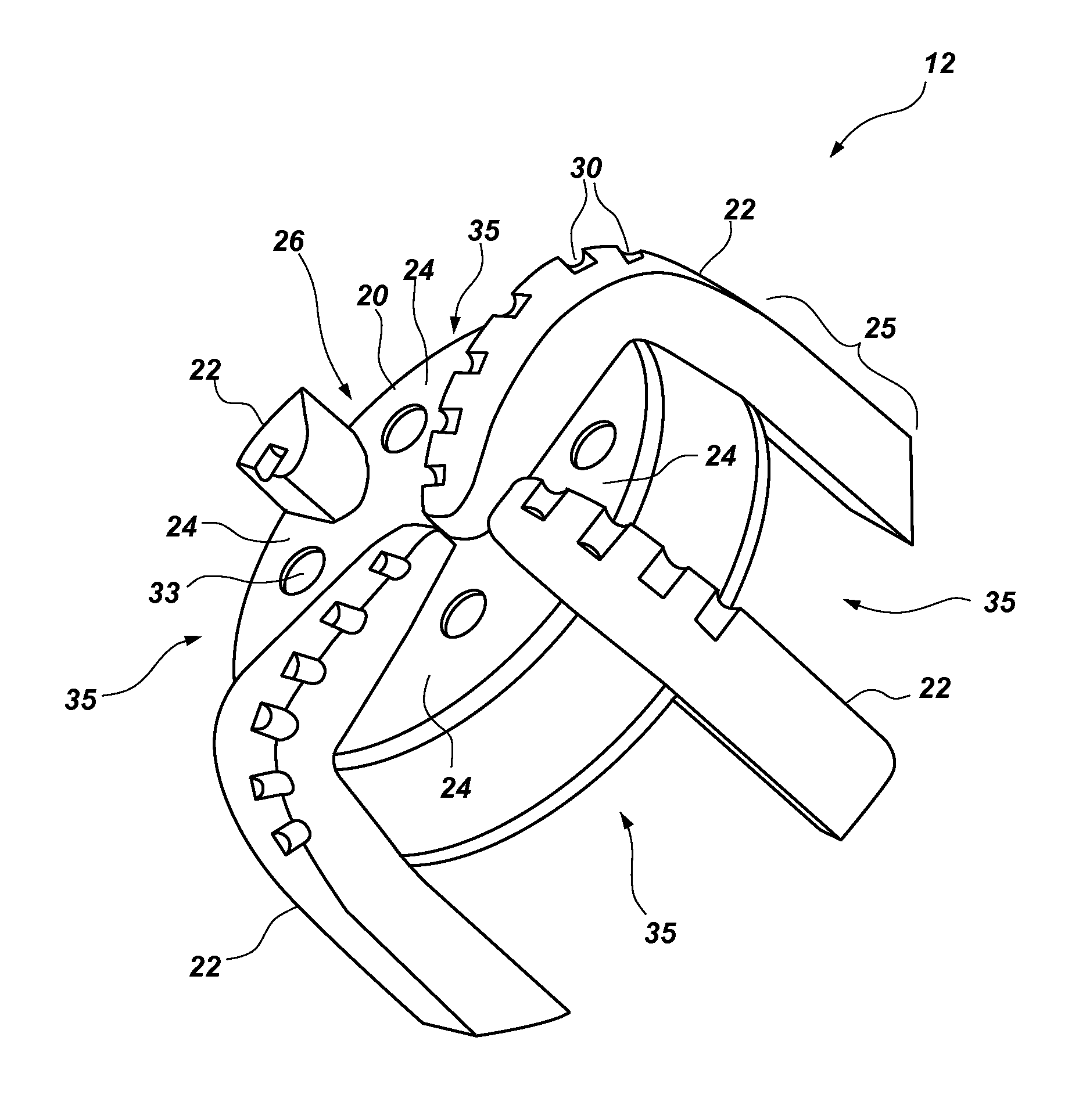
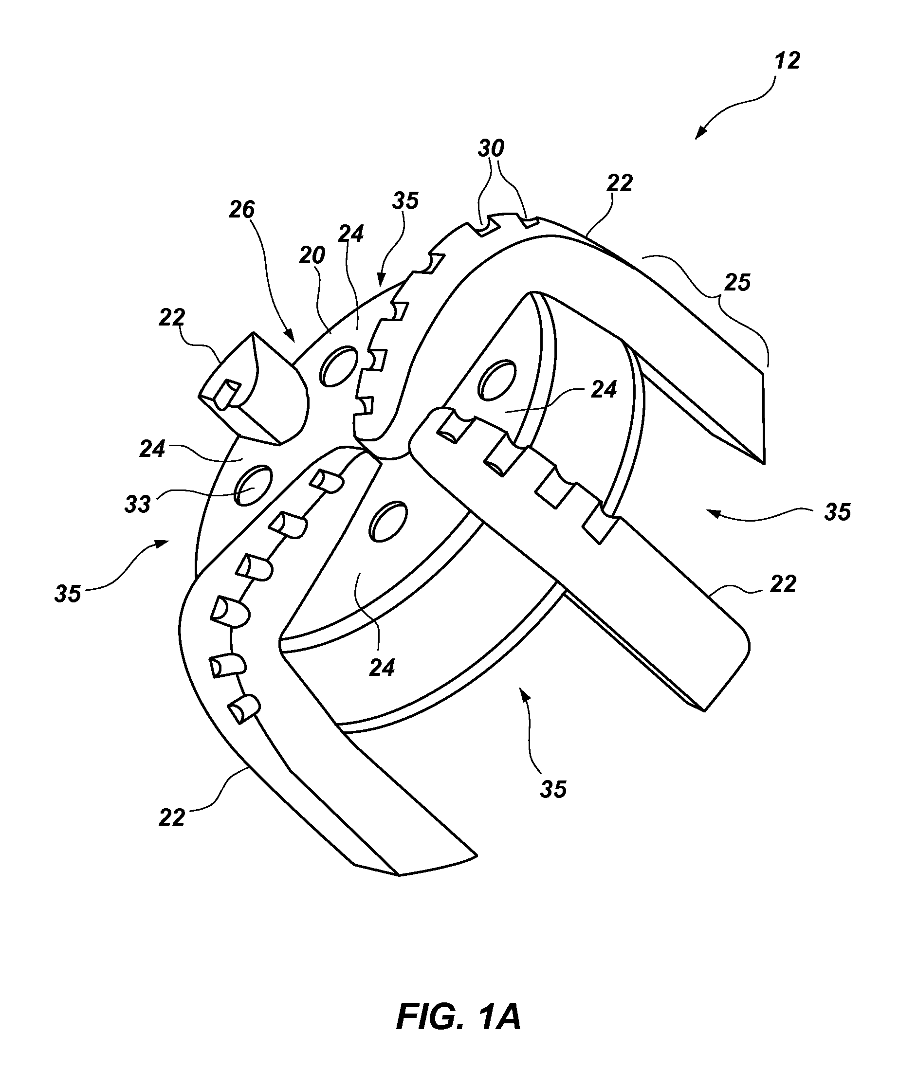
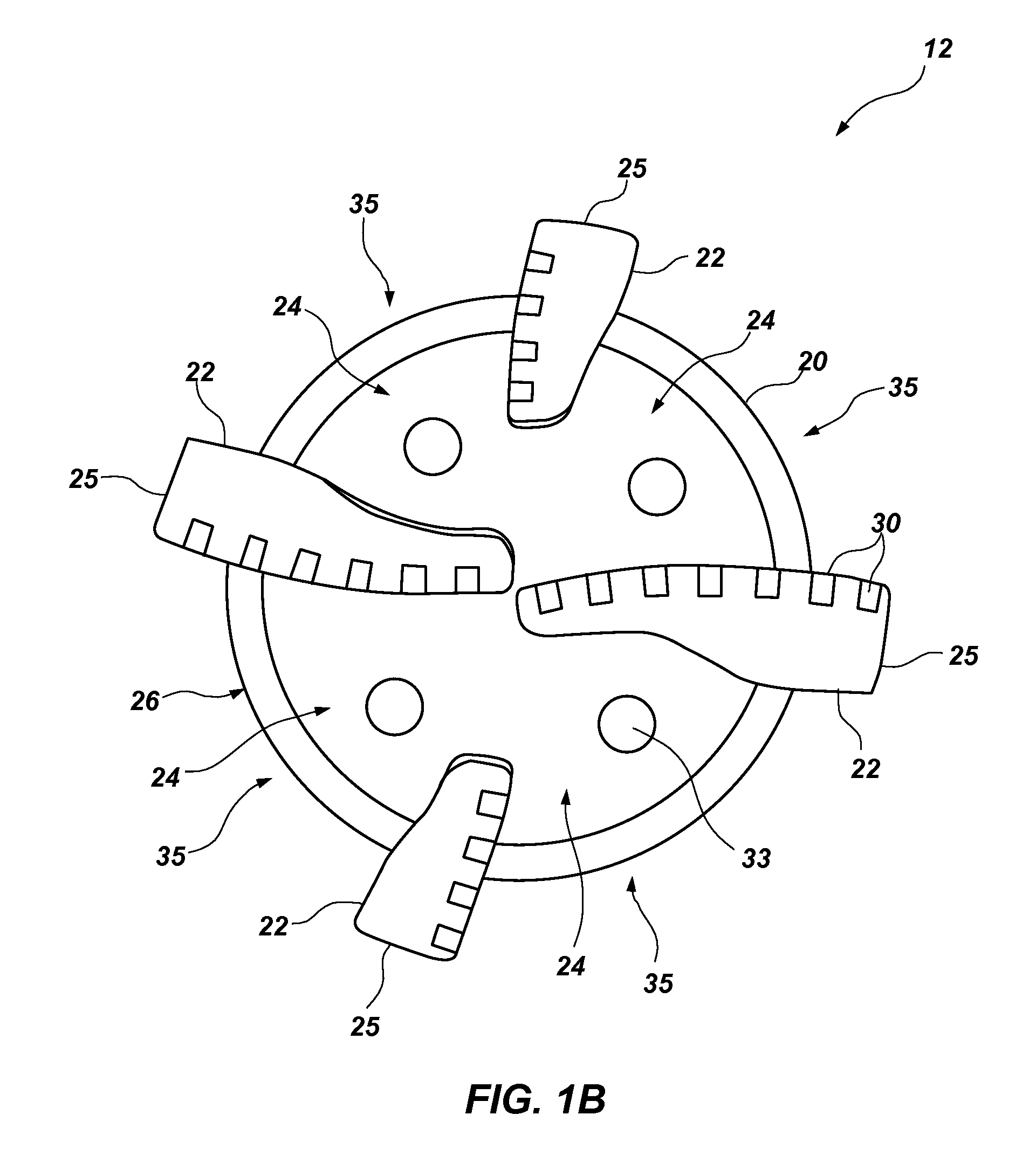
[0110]FIGS. 1A-1D illustrate a casing bit 12 according to the present invention. As shown in FIG. 1A, casing bit 12 includes a nose portion 20 and generally radially extending blades 22, forming fluid courses 24 therebetween extending to junk slots 35 between circumferentially adjacent blades 22. Blades 22 may also include pockets 30, which may be configured to carry cutting elements (not shown), such as, for instance, polycrystalline diamond cutting elements. Generally, a cutting element may comprise a superabrasive region that is bonded to a substrate. A particular cutting element that is used in rotary drill bits is a polycrystalline diamond compact (“PDC”) cutter. Rotary drag bits employing PDC cutters have been employed for several decades. PDC cutters are typically comprised of a disc-shaped diamond “table” formed on and bonded under a high-pressure and high-temperature (HPHT) process to a supporting substrate such as cemented tungsten carbide (WC), although other configuratio...


PUM


Abstract

A casing bit, which may comprise a composite structure, for drilling a casing section into a subterranean formation, and which may include a portion configured to be drilled therethrough, is disclosed. Cutting elements and methods of use are disclosed. Adhesive, solder, electrically disbonding material, and braze affixation of a cutting element are disclosed. Differing abrasive material amount, characteristics, and size of cutting elements are disclosed. Telescoping casing sections and bits are disclosed. Aspects and embodiments are disclosed including: at least one gage section extending from a nose portion, at least one rotationally trailing groove formed in at least one of the plurality of blades, a movable blade, a leading face comprising superabrasive material, at least one of a drilling fluid nozzle and a sleeve, grooves for preferential failure, at least one rolling cone affixed to the nose portion, at least one sensor, discrete cutting element retention structures, and percussion inserts.

Description

CROSS-REFERENCE TO RELATED APPLICATION[0001]This application is a continuation of U.S. patent application Ser. No. 12 / 129,308, filed May 29, 2008, which is a divisional of application Ser. No. 10 / 783,720, filed Feb. 19, 2004, now U.S. Pat. No. 7,395,882, issued Jul. 8, 2008, the disclosure of each of which applications is incorporated by reference herein in its entirety.BACKGROUND[0002]1. Field of the Invention[0003]The present invention relates generally to drilling a subterranean borehole and, more specifically, drilling structures disposed on the end of a casing or liner.[0004]2. State of the Art[0005]The drilling of wells for oil and gas production conventionally employs longitudinally extending sections or so-called “strings” of drill pipe to which, at one end, is secured a drill bit of a larger diameter. After a selected portion of the borehole has been drilled, the borehole is usually lined or cased with a string or section of casing. Such a casing or liner usually exhibits a...

Claims


Application Information

Patent Timeline
Patent Type & Authority Applications(United States)
IPC IPC(8): E21B17/14E21B10/56E21B7/20E21B10/26E21B10/54E21B10/55E21B10/567E21B17/07
CPCE21B7/20E21B10/08E21B10/26E21B17/14E21B10/55E21B10/567E21B17/07E21B10/42
Inventor OLDHAM, JACK T.SINOR, L. ALLENMCCLAIN, ERIC E.LAING, ROBERT A.TURNER, EVAN C.DYKSTRA, MARK W.SULLIVAN, ERIC C.
Owner BAKER HUGHES INC
Learn More