Fuel Reforming Apparatus And Fuel Cell System

a fuel cell and reforming technology, applied in the direction of metal/metal-oxide/metal-hydroxide catalysts, physical/chemical process catalysts, bulk chemical production, etc., can solve the problem that the system may exhibit only poor reforming properties at start-up, unsatisfactory starting-up properties for the use of vehicles requiring excellent starting-up properties, and low catalytic activity, etc. problem, to achieve the effect of excellent hydrocarbon conversion rate, excellent h2+

Inactive Publication Date: 2011-09-15
NISSAN MOTOR CO LTD
View PDF0 Cites 17 Cited by
  • Summary
  • Abstract
  • Description
  • Claims
  • Application Information

AI Technical Summary

Benefits of technology

[0004]The system using hydrocarbon as a hydrogen source has an advantage in that the raw material is easily available and inexpensive. However, the system may exhibit only poor reforming properties at start-up. Specifically, the system is at a low temperature immediately after starting up the system and hence the catalytic activity is low, and the unreacted hydrocarbon may remain or the concentration of hydrogen or carbon monoxide in the reformed gas cannot reach the equilibrium composition in a steady state. The fuel reforming system can be mounted on a fuel cell car, but it has unsatisfactory starting-up properties for the use in vehicle requiring excellent starting-up properties.
[0005]The present inventor has made close studies on the properties of the reforming catalyst. As a result, they have paid attention to the fact that the reforming reaction of hydrocarbon consists of a hydrocarbon decomposition reaction which decomposes hydrocarbon into CHx and a steam reforming reaction which forms carbon monoxide and hydrogen. Further, they have found that a combination of a catalyst having excellent hydrocarbon decomposition performance and a catalyst having such excellent steam reforming performance that H2O is activated to facilitate steam reforming can improve the reforming efficiency. Furthermore, they have confirmed that, when a catalyst packed portion of a fuel reforming apparatus contains therein a fuel reforming catalyst (I) having excellent hydrocarbon conversion rate and a fuel reforming catalyst (II) having excellent H2+CO formation rate, excellent starting-up properties even under conditions at low temperatures and improved robustness can be obtained, and the present invention has been completed.
[0006]Specifically, the present invention provides a fuel reforming apparatus which comprises a catalyst packed portion containing therein a fuel reforming catalyst (I) having excellent hydrocarbon conversion rate and a fuel reforming catalyst (II) having excellent H2+CO formation rate.

Problems solved by technology

However, the system may exhibit only poor reforming properties at start-up.
Specifically, the system is at a low temperature immediately after starting up the system and hence the catalytic activity is low, and the unreacted hydrocarbon may remain or the concentration of hydrogen or carbon monoxide in the reformed gas cannot reach the equilibrium composition in a steady state.
The fuel reforming system can be mounted on a fuel cell car, but it has unsatisfactory starting-up properties for the use in vehicle requiring excellent starting-up properties.

Method used


Image

  • Fuel Reforming Apparatus And Fuel Cell System
  • Fuel Reforming Apparatus And Fuel Cell System
  • Fuel Reforming Apparatus And Fuel Cell System

Examples


first embodiment

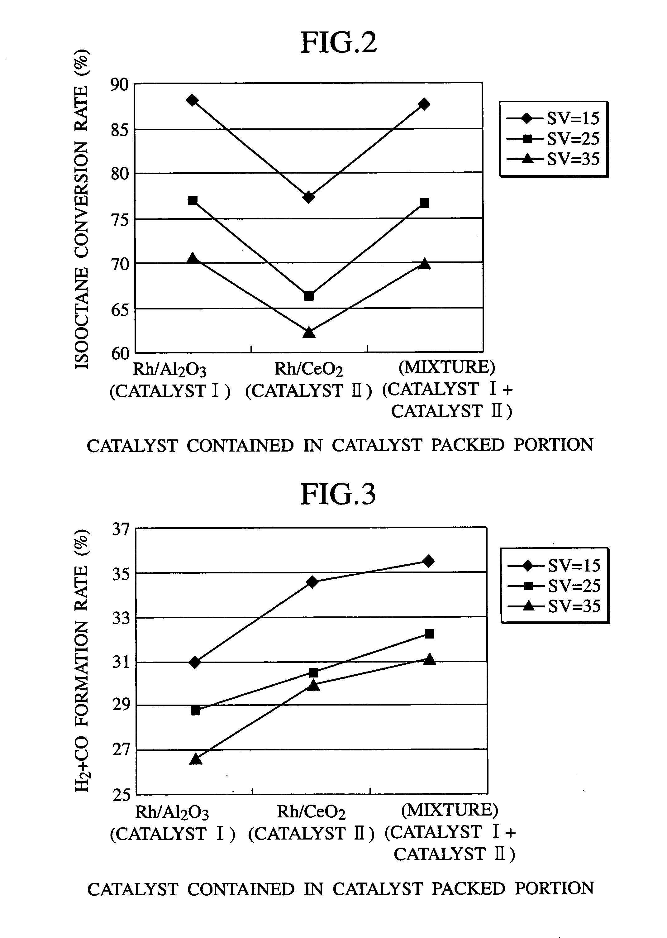
[0018]The first embodiment of the present invention is directed to a fuel reforming apparatus. The fuel reforming apparatus is an apparatus which reforms hydrocarbon contained in a fuel to form hydrogen, and has a catalyst packed portion which is a reaction tube packed with a catalyst. The catalyst packed portion has one feed inlet or a plurality of feed inlets for feeding at least fuel gas, oxidizing gas required for a reforming reaction, such as air, and steam gas, and a discharge outlet for discharging the reformed gas. The fuel reforming apparatus according to the first embodiment of the present invention has a characteristic feature such that the catalyst packed portion contains therein fuel reforming catalyst (I) having excellent hydrocarbon conversion rate and fuel reforming catalyst (II) having excellent H2+CO formation rate.

[0019]In the reforming reaction of hydrocarbon on a fuel reforming catalyst, when, for example, isooctane C8H18 [(CH3(CH3)2CCH2(CH3)CHCH3)] is used as a...

second embodiment

[0066]The second embodiment of the present invention is directed to a polymer electrolyte fuel cell system to which the fuel reforming apparatus according to the first embodiment is applied.

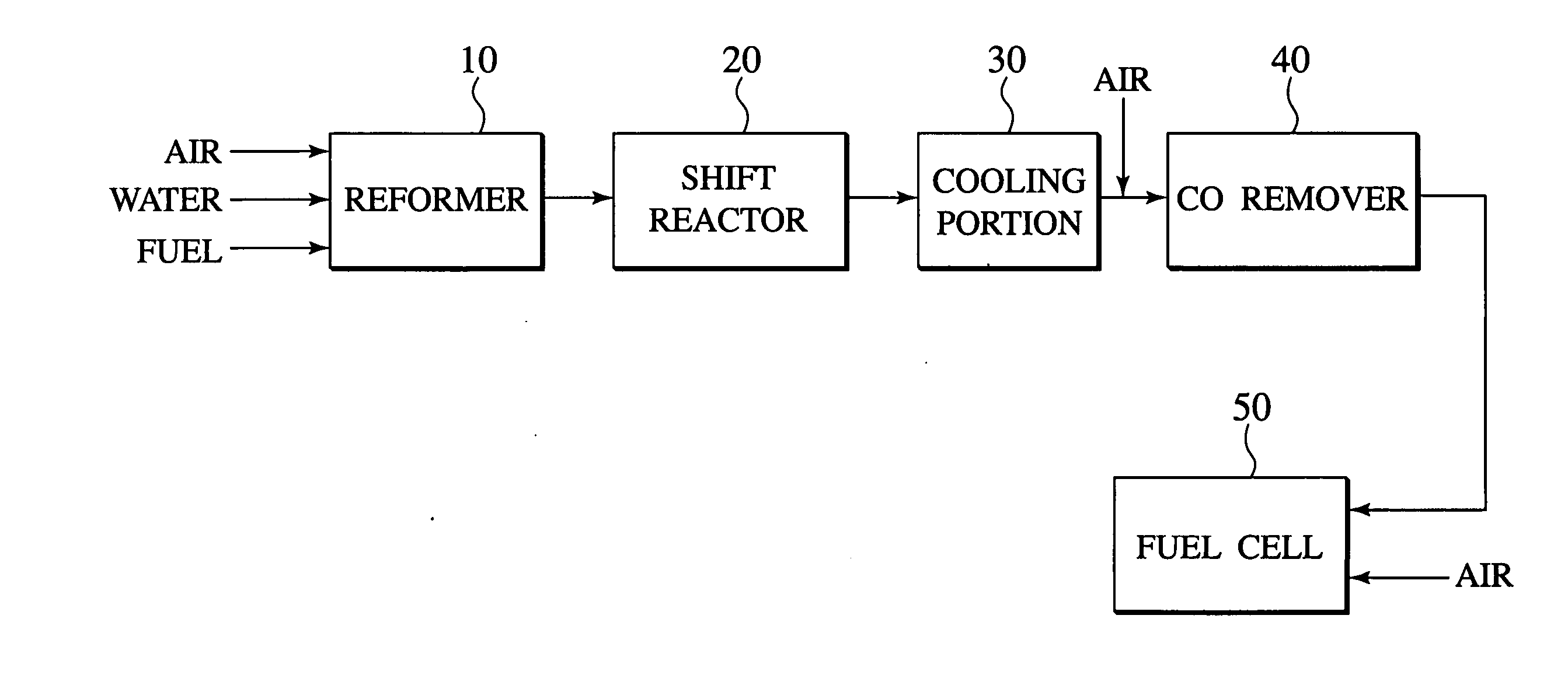
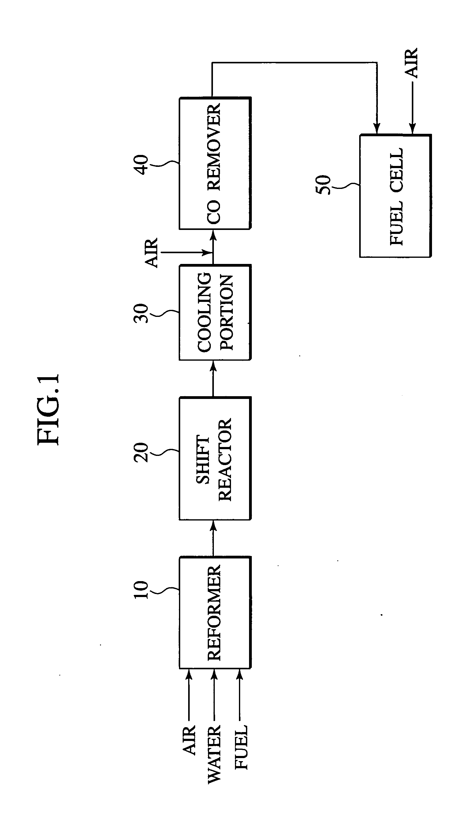
[0067]FIG. 1 shows a schematic construction of the polymer electrolyte fuel cell system. The system comprises a fuel reforming apparatus 10 according to the first embodiment, a shift reactor 20 for reducing carbon monoxide contained in the discharged gas from the fuel reforming apparatus 10 through a water-gas-shift reaction, a carbon monoxide removing apparatus 40 for removing carbon monoxide contained in the discharged gas, and a polymer electrolyte fuel cell 50. If necessary, the system may comprise a cooling portion 30, disposed between the shift reactor 20 and the carbon monoxide removing apparatus 40, for cooling the discharged gas from the shift reactor 20.

[0068]In the polymer electrolyte fuel cell system using, for example, isooctane as a fuel, as shown in FIG. 1, isooctane is reformed by...

preparation example 1

Catalyst Preparation Example 1

[0073]Al2O3 (BET specific surface area: 200 m2 / g) was used as a carrier, and the carrier was added to 0.36 liter of a 0.058 M aqueous solution of rhodium nitrate so that the carrier was impregnated with a rhodium element, and the resultant mixture was satisfactorily stirred, and then dried for one day, followed by baking at 500° C., to obtain catalyst 1.

[0074]Subsequently, 0.47 liter of water was added to catalyst 1, and the catalyst was wet-milled to prepare a slurry, and the slurry was applied to a honeycomb substrate made of ceramic (6 mils, 400 cells; hereinafter, referred to as “cerahoneycomb”) and dried at 120° C., and baked in air at 400° C. to obtain monolith catalyst 1. In the milling, a commercially available ball-type vibration mill was used, and the ball diameter, the milling time, the amplitude of vibration, and the number of vibration were adjusted so that the resultant slurry has an average particle size of 2 to 3 μm, and catalyst 1 was s...


PUM

PropertyMeasurementUnit
operating temperatureaaaaaaaaaa
massaaaaaaaaaa
mass ratioaaaaaaaaaa

Abstract

A fuel reforming apparatus includes a catalyst packed portion containing therein fuel reforming catalyst (I) having excellent hydrocarbon conversion rate and fuel reforming catalyst (II) having excellent H2+CO formation rate. Each of catalyst (I) and catalyst (II) especially preferably includes rhodium supported thereon. When the carrier for catalyst (I) is aluminum oxide and the carrier for catalyst (II) is cerium oxide, the hydrogen generation efficiency is excellent particularly even at start-up.

Description

TECHNICAL FIELD[0001]The present invention relates to a fuel reforming apparatus which reforms hydrocarbon gas to obtain hydrogen gas, and a fuel cell system using the fuel reforming apparatus, a hydrogen generating apparatus, and a vehicle having the system mounted thereon.BACKGROUND ART[0002]A polymer electrolyte fuel cell can achieve high current density even at relatively low temperatures, and is expected as a mobile power source for vehicle. As a hydrogen source for the polymer electrolyte fuel cell, a system utilizing pure hydrogen is mainly studied. This system requires no consideration for the effect of carbon monoxide on the polymer electrolyte fuel cell, and can offer a simple construction.[0003]Further, there is a system using hydrocarbon as a hydrogen source. For example, a system using a hydrocarbon reforming catalyst comprising a catalyst which comprises at least one element selected from the group consisting of titanium, aluminum, silicon, zirconium, nickel, iron, cob...

Claims


Application Information

Patent Timeline
Patent Type & Authority Applications(United States)
IPC IPC(8): H01M8/06B01J8/04C01B3/40B01J23/42B01J23/44B01J23/46B01J23/63C01B3/48H01M8/00H01M8/10
CPCC01B3/40C01B3/48C01B2203/0244C01B2203/0283C01B2203/044C01B2203/047Y02E60/50C01B2203/0872C01B2203/1023C01B2203/1082C01B2203/142H01M8/0618H01M2250/00C01B2203/066Y02P20/52
Inventor MARUYAMA, TAKAO
Owner NISSAN MOTOR CO LTD
Why Eureka
Try Eureka