
Fuel cell system

Active Publication Date: 2011-09-01
TOYOTA JIDOSHA KK
View PDF3 Cites 14 Cited by
  • Summary
  • Abstract
  • Description
  • Claims
  • Application Information

AI Technical Summary

Benefits of technology

[0008]The present invention provides a fuel cell system that can prevent the discharge valve from being frozen shut during cold start of a fuel cell.
[0010]According to the above aspect, water is generated in the fuel cell and the temperature of the water is increased as a result of power generation in the fuel cell in the first period, and the generated water with an increased temperature is discharged from the fuel cell into the circulating system by driving the pump in the second period. Because the temperature of the flow path from the fuel cell to the discharge valve can be increased by the generated water that is discharged, the generated water that is discharged during cold start is prevented from freezing. As a result, opening failure of the discharge valve can be prevented without providing an additional heater or the like.

Problems solved by technology

In a low-temperature environment below 0° C., if water discharged from the fuel cell into the circulating system adheres to the discharge valve or the inner surfaces of the flow path from the fuel cell to the discharge valve, the water may freeze and cause an opening failure of the discharge valve.
In particular, an opening failure of the discharge valve that is caused by freezing of the discharged water tends to occur during startup of the fuel cell because the amount of heat in the generated water is small.
Providing a heater that is used to melt frozen parts as a measure against such freezing leads to an increase of equipment and cost for the entire fuel cell system.
The measure that is described in JP-A-2003-203665 is not necessarily effective because it does not relate to the time of startup of a fuel cell, when freezing is most likely to occur.

Method used


Image

  • Fuel cell system
  • Fuel cell system
  • Fuel cell system

Examples


Embodiment Construction

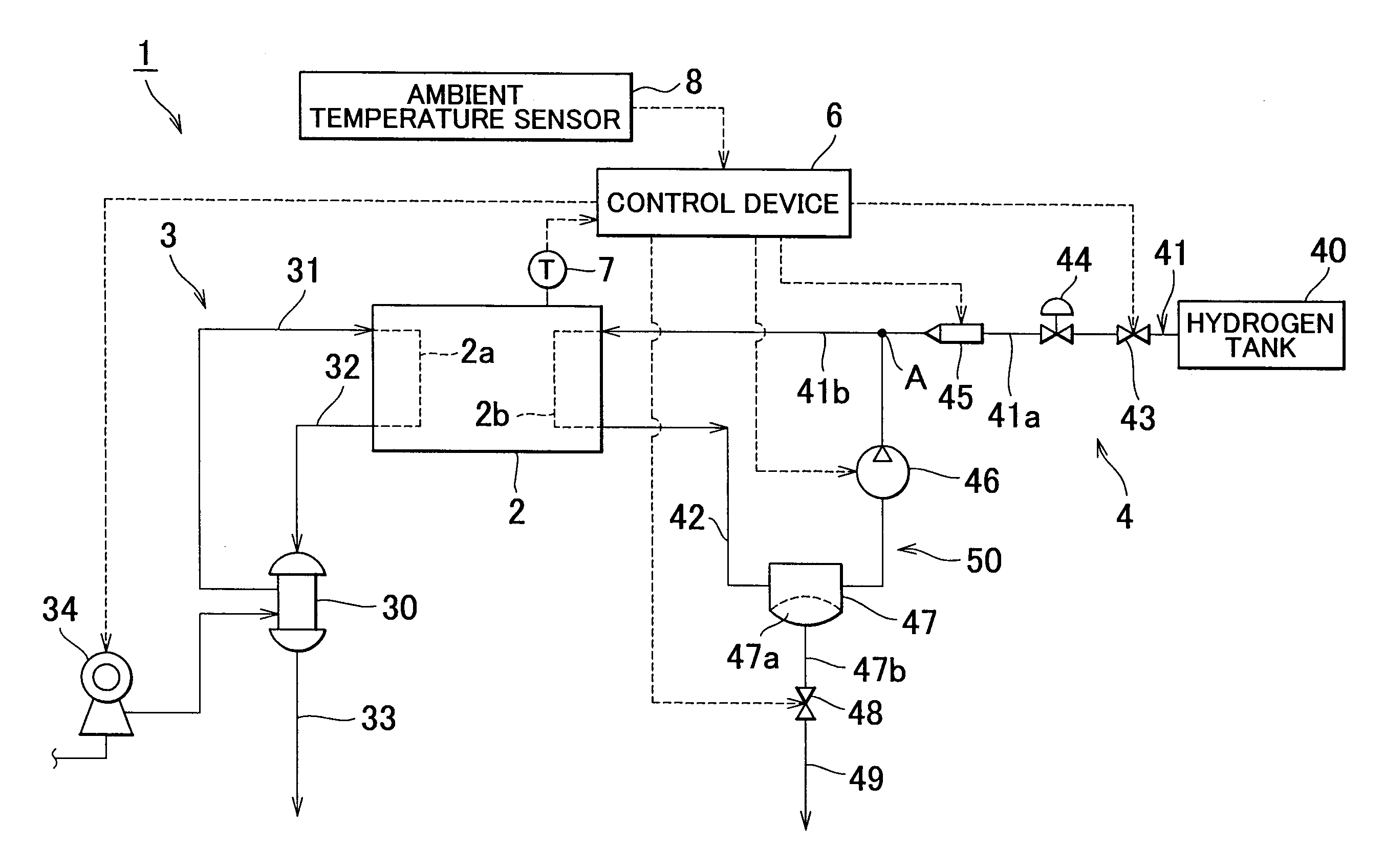
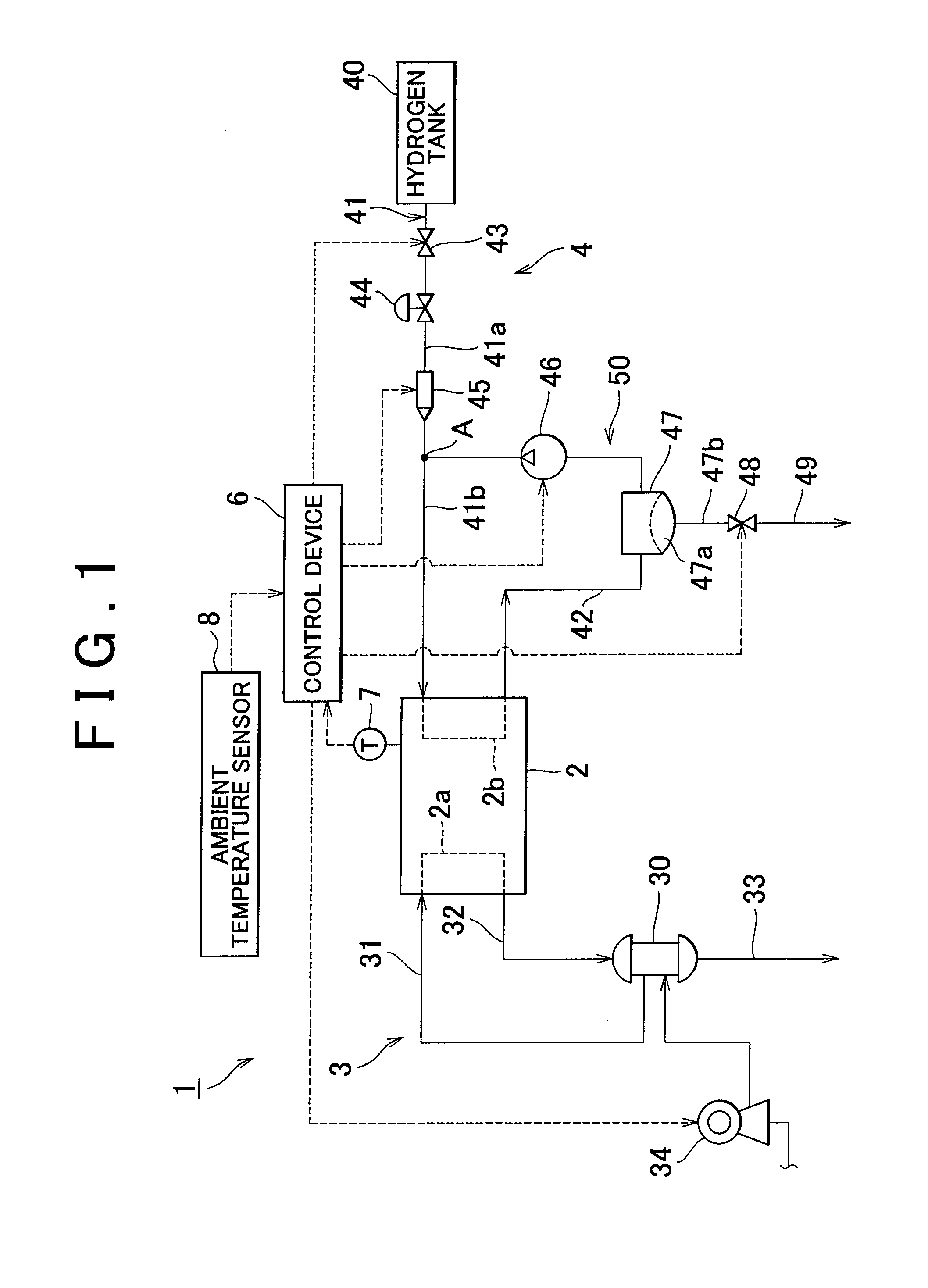
[0016]A fuel cell system according to one embodiment of the present invention will be described below with reference to the accompanying drawings.

[0017]As shown in FIG. 1, a fuel cell system 1 includes a fuel cell 2, an oxygen gas piping system 3, a fuel gas piping system 4, and a control device 6. The fuel cell system 1, which may be mounted on a vehicle to supply electric power to a traction motor, is applicable to any mobile objects such as boats, airplanes, trains and walking robots in addition to vehicles. The fuel cell system 1 may also be applied to stationary power generation systems that are used as a power generating facility for an architectural structure (residence, building, etc.).

[0018]The fuel cell 2 may be a polymer electrolyte type, for example, and has a stack structure in which a plurality of unit cells are stacked on top of each other. A polymer electrolyte type unit cell includes a cathode on one side of an electrolyte that is composed of an ion-exchange membran...


PUM


Abstract

A fuel cell system includes a fuel cell; a circulating system that circulates and supplies fuel off-gas discharged from the fuel cell to the fuel cell; a pump that pumps a fluid in the circulating system; a discharge valve through which the fluid in the circulating system is discharged to the outside; and a control device that controls the pump and the discharge valve. If operation of the fuel cell is started in a cold environment, the control device executes a control to start power generation in the fuel cell for a first period before activating the pump and executes a control to drive the pump while the discharge valve is closed for a second period.

Description

INCORPORATION BY REFERENCE[0001]The disclosure of Japanese Patent Application No. 2010-044455 filed on Mar. 1, 2010 including the specification, drawings and abstract is incorporated herein by reference in its entirety.BACKGROUND OF THE INVENTION[0002]1. Field of the Invention[0003]The present invention relates to a fuel cell system that is equipped with a fuel gas circulating system.[0004]2. Description of the Related Art[0005]Conventional fuel cell systems generally include a fuel cell, which is supplied with a fuel gas that contains hydrogen and an oxidation gas that contains oxygen, to generate electric power and a means to prevent freezing in a low-temperature environment. For example, in Japanese Patent Application Publication No. 2003-203665 (JP-A-2003-203665), dry air is fed into a flow rate control valve provided in an oxidation gas supply system to blow off water droplets thereon when the fuel cell is stopped.[0006]A conventional fuel cell system may also be provided with ...

Claims


Application Information

Patent Timeline
IPC IPC(8): H01M8/06
CPCH01M8/04097H01M8/04164Y02E60/50H01M8/0432H01M8/04253
Inventor ITOGA, MICHITARO
Owner TOYOTA JIDOSHA KK
Learn More