
Ocean Thermal Energy Conversion Plant

a technology of thermal energy and power plants, applied in indirect heat exchangers, machines/engines, light and heating apparatus, etc., can solve the problems of increasing the cost of fossil fuel extraction, and depleting fossil fuel sources at an accelerating ra

Active Publication Date: 2011-07-21
THE ABELL FOUND INC
View PDF99 Cites 43 Cited by
  • Summary
  • Abstract
  • Description
  • Claims
  • Application Information

AI Technical Summary

Benefits of technology

Further Aspects of the invention relate to an offshore OTEC power plant having improved overall efficiencies with reduced parasitic loads, greater stability, lower construction and operating costs, and improved environmental footprint. Other aspects include large volume water conduits that are integral with the floating structure. Modularity and compartmentation of the multi-stage OTEC heat engine reduces construction and maintenance costs, limits off-grid operation and improves operating performance. Still further aspects provide for a floating platform having structurally integrated heat exchange compartments and provides for minimal movement of the platform due to wave action. The integrated floating platform may also provide for efficient flow of the warm water or cool water through the multi-stage heat exchanger, increasing efficiency and reducing the parasitic power demand. Aspects of the invention can promote an environmentally neutral thermal footprint by discharging warm and cold water at appropriate depth / temperature ranges. Energy extracted in the form of electricity reduces the bulk temperature to the ocean.
In a further aspect, the first deck portion further comprises a first stage warm water structural passage forming a high volume warm water conduit. The first deck portion also comprises a first stage working fluid passage arranged in cooperation with the first stage warm water structural passage to warm a working fluid to a vapor. The first deck portion also comprises a first stage warm water discharge directly coupled to a second stage warm water structural passage. The second stage warm water structural passage forms a high volume warm water conduit and comprises a second stage warm water intake coupled to the first stage warm water discharge. The arrangement of the first stage warm water discharge to the second stage warm water intake provides minimal pressure loss in the warm water flow between the first and second stage. The first deck portion also comprises a second stage working fluid passage arranged in cooperation with the second stage warm water structural passage to warm the working fluid to a vapor. The first deck portion also comprises a second stage warm water discharge.
In a further aspect, the submerged portion further comprises a second deck portion comprising a first stage cold water structural passage forming a high volume cold water conduit. The first stage cold water passage further comprises a first stage cold water intake. The second deck portion also comprises a first stage working fluid passage in communication with the first stage working fluid passage of the first deck portion. The first stage working fluid passage of the second deck portion in cooperation with the first stage cold water structural passage cools the working fluid to a liquid. The second deck portion also comprises a first stage cold water discharge directly coupled to a second stage cold water structural passage forming a high volume cold water conduit. The second stage cold water structural passage comprises a second stage cold water intake. The first stage cold water discharge and the second stage cold water intake are arranged to provide minimal pressure loss in the cold water flow from the first stage cold water discharge to the second stage cold water intake. The second deck portion also comprises a second stage working fluid passage in communication with the second stage working fluid passage of the first deck portion. The second stage working fluid passage in cooperation with the second stage cold water structural passage cool the working fluid within the second stage working fluid passage to a liquid. The second deck portion also comprises a second stage cold water discharge.
A still further aspect of the invention can include a high-volume, low-velocity heat exchange system for use in an ocean thermal energy conversion power plant, comprising: a first stage cabinet that further comprises a first water flow passage for heat exchange with a working fluid; and a first working fluid passage; and a second stage cabinet coupled to the first stage cabinet, that further comprises a second water flow passage for heat exchange with a working fluid and coupled to the first water flow passage in a manner to minimize pressure drop of water flowing from the first water flow passage to the second water flow passage; and a second working fluid passage. The first and second stage cabinets comprise structural members of the power plant.
Aspects of the invention may have one or more of the following advantages: OTEC power production requires little to no fuel costs for energy production; the low pressures and low temperatures involved in the OTEC heat engine reduce component costs and require ordinary materials compared to the high-cost, exotic materials used in high pressure, high temperature power generation plants; plant reliability is comparable to commercial refrigeration systems, operating continuously for several years without significant maintenance; reduced construction times compared to high pressure, high temperature plants; and safe, environmentally benign operation and power production. Additional advantages may include, increased net efficiency compared to traditional OTEC systems, lower sacrificial electrical loads; reduced pressure loss in warm and cold water passages; modular components; less frequent off-grid production time; minimal heave and reduced susceptibility to wave action and unseating of the cold water pipe connection; discharge of cooling water below surface levels, intake of warm water free from interference from cold water discharge.

Problems solved by technology

At the same time, traditional sources of energy, namely fossil fuels, are being depleted at an accelerating rate and the cost of exploiting fossil fuels continues to rise.
Environmental and regulatory concerns are exacerbating that problem.
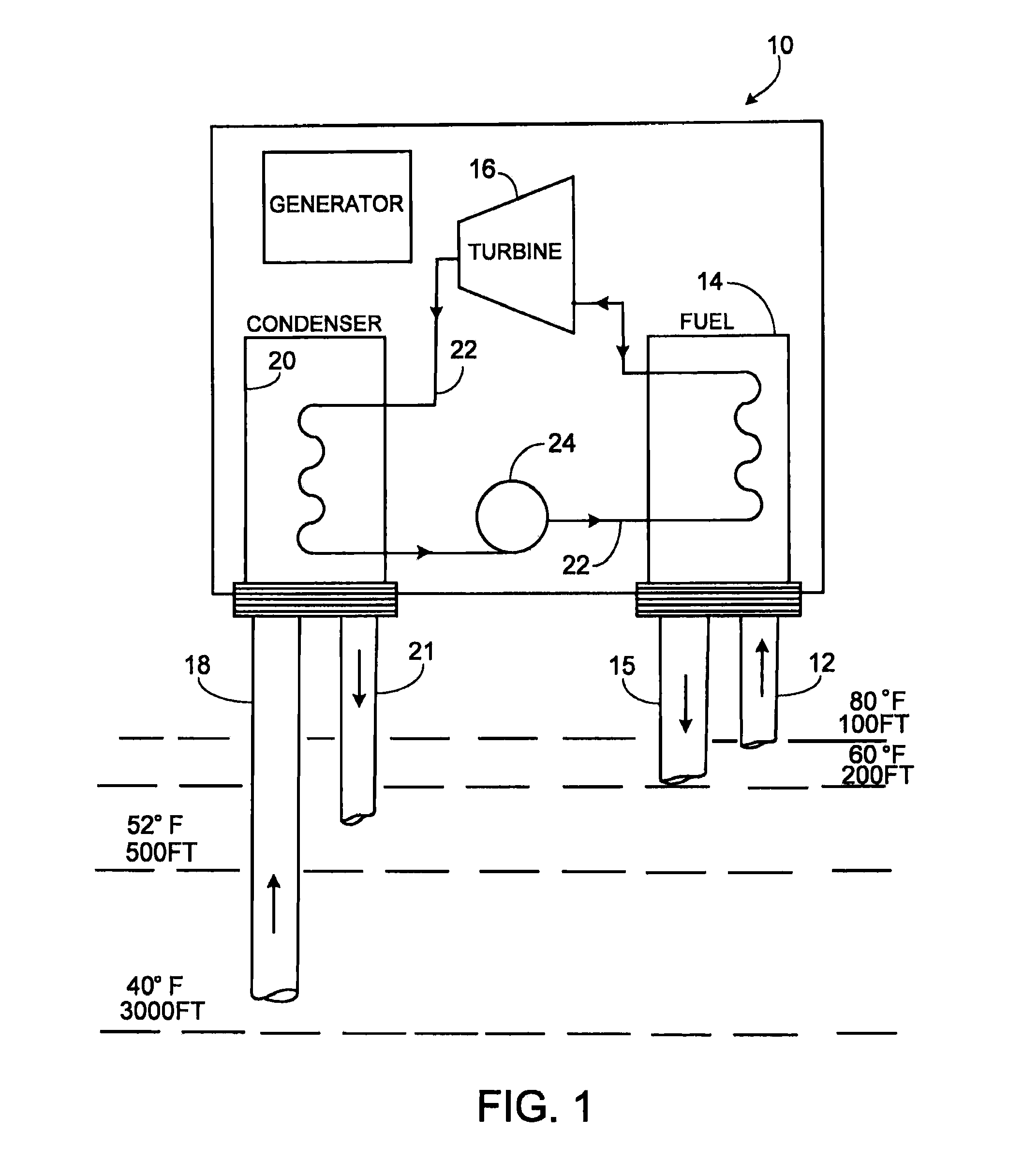
An OTEC power plant, however, has a low thermodynamic efficiency compared to more traditional, high pressure, high temperature power generation plants.
On this basis, the low overall net efficiency of an OTEC power plant converting the thermal energy stored in the ocean surface waters to net electric energy has not been a commercially viable energy production option.
An additional factor resulting in further reductions in overall thermodynamic efficiency is the loss associated with providing necessary controls on the turbine for precise frequency regulation.
This introduces pressure losses in the turbine cycle that limit the work that can be extracted from the warm sea water.
This low OTEC net efficiency compared with efficiencies typical of heat engines that operate at high temperatures and pressures has led to the widely held assumption by energy planners that OTEC power is too costly to compete with more traditional methods of power production.
Indeed, the parasitic electrical power requirements are particularly important in an OTEC power plant because of the relatively small temperature difference between the hot and cold water.
Increasing any one of these factors can increase the parasitic load on the OTEC plant, thereby decreasing net efficiency.
In addition to the relatively low efficiencies with seemingly inherent large parasitic loads, the operating environment of OTEC plants presents design and operating challenges that also decrease the commercial viability of such operations.
Suspending a large diameter pipe from an offshore structure presents stability, connection and construction challenges which have previously driven OTEC costs beyond commercial viability.
Additionally, a pipe having significant length to diameter ratio that is suspended in a dynamic ocean environment can be subjected to temperature differences and varying ocean currents along the length of the pipe.
Stresses from bending and vortex shedding along the pipe also present challenges.
And surface influences such as wave action present further challenges with the connection between the pipe and floating platform.

Method used


Image

  • Ocean Thermal Energy Conversion Plant
  • Ocean Thermal Energy Conversion Plant
  • Ocean Thermal Energy Conversion Plant

Examples


example

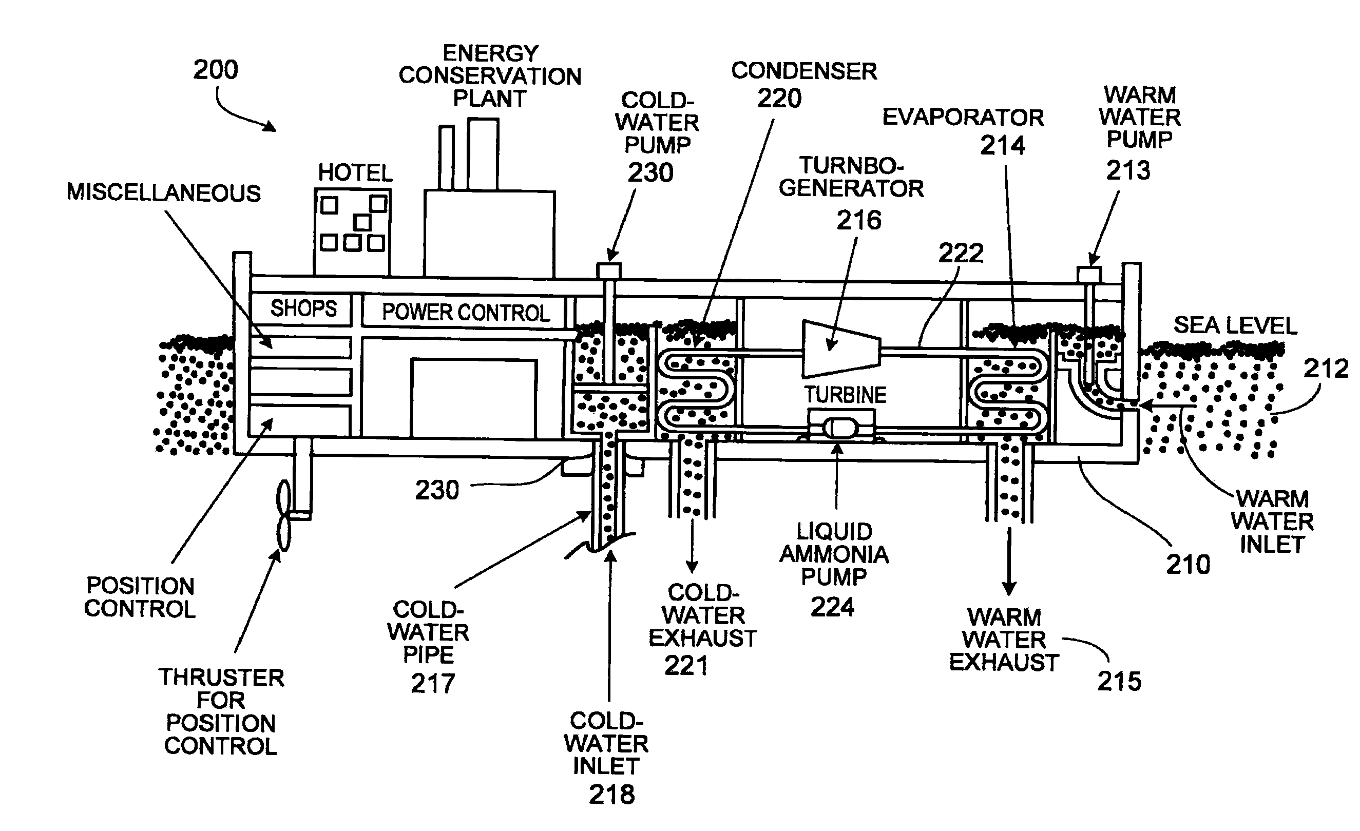
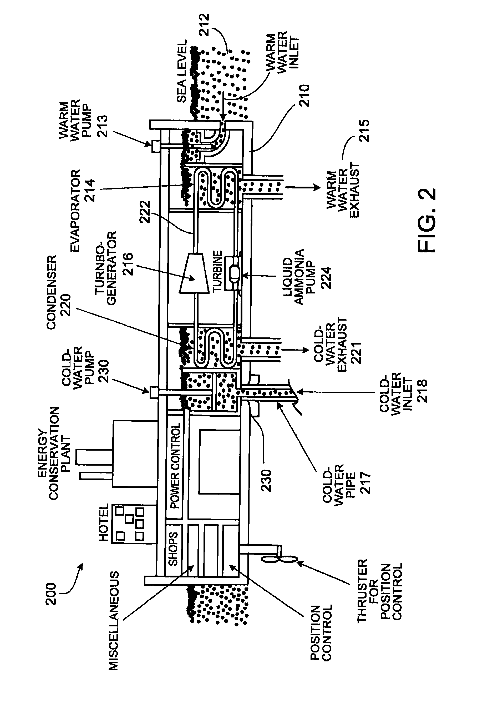
Aspects of the present invention provide an integrated multi-stage OTEC power plant that will produce electricity using the temperature differential between the surface water and deep ocean water in tropical and subtropical regions. Aspects eliminate traditional piping runs for sea water by using the off-shore vessel's or platform's structure as a conduit or flow passage. Alternatively, the warm and cold sea water piping runs can use conduits or pipes of sufficient size and strength to provide vertical or other structural support to the vessel or platform. These integral sea water conduit sections or passages serve as structural members of the vessel, thereby reducing the requirements for additional steel. As part of the integral sea water passages, multi-stage cabinet heat exchangers provide multiple stages of working fluid evaporation without the need for external water nozzles or piping connections. The integrated multi-stage OTEC power plant allows the warm and cold sea water to...

example 2

An offshore OTEC spar platform includes four separate power modules, each generating about 25 MWe Net at the rated design condition. Each power module comprises four separate power cycles or cascading thermodynamic stages that operate at different pressure and temperature levels and pick up heat from the sea water system in four different stages. The four different stages operate in series. The approximate pressure and temperature levels of the four stages at the rated design conditions (Full Load—Summer Conditions) are:

Turbine inletCondenserPressure / Temp.Pressure / Temp.(Psia) / (° F.)(Psia) / (° F.)1 Stage137.9 / 74.7 100.2 / 56.52″ Stage132.5 / 72.493.7 / 533′ Stage127.3 / 70.2 87.6 / 49.54″ Stage122.4 / 68 81.9 / 46

The working fluid is boiled in multiple evaporators by picking up heat from warm sea water (WSW). Saturated vapor is separated in a vapor separator and led to an ammonia turbine by STD schedule, seamless carbon steel pipe. The liquid condensed in the condenser is pumped back to the evapora...


PUM


Abstract

An offshore power generation structure comprising a submerged portion having a first deck portion comprising an integral multi-stage evaporator system, a second deck portion comprising an integral multi-stage condensing system, a third deck portion housing power generation equipment, cold water pipe; and a cold water pipe connection. The heat exchangers in the evaporator and condenser systems include a multi-stage cascading heat exchange system. Warm water conduits in the first deck portion and cold water conduits in the second deck portion are integral to the structure of the submerged portion of the offshore platform.

Description

TECHNICAL FIELDThis invention relates to ocean thermal energy conversion power plants and more specifically to floating minimum heave platform, multi-stage heat engine, ocean thermal energy conversion power plants.BACKGROUNDEnergy consumption and demand throughout the world has grown at an exponential rate. This demand is expected to continue to rise, particularly in developing countries in Asia and Latin America. At the same time, traditional sources of energy, namely fossil fuels, are being depleted at an accelerating rate and the cost of exploiting fossil fuels continues to rise. Environmental and regulatory concerns are exacerbating that problem.Solar-related renewable energy is one alternative energy source that may provide a portion of the solution to the growing demand for energy. Solar-related renewable energy is appealing because, unlike fossil fuels, uranium, or even thermal “green” energy, there are few or no climatic risks associated with its use. In addition, solar rela...

Claims


Application Information

Patent Timeline
IPC IPC(8): F03G7/05
CPCF03G7/05Y02E10/34F28D15/00F01K19/02F01K7/16Y02E10/30
Inventor KRULL, RUSSSHAPIRO, LAURENCE JAYROSS, JONATHAN M.
Owner THE ABELL FOUND INC
Learn More