
Clamping device for a cutting insert

Inactive Publication Date: 2011-07-07
TAEGUTEC
View PDF9 Cites 7 Cited by
  • Summary
  • Abstract
  • Description
  • Claims
  • Application Information

AI Technical Summary

Benefits of technology

[0017]The insert clamp according to the present invention has the following technical effects.
[0018]The insert clamp according to the present invention has an effect to prevent wearing at the contact point and provide a durable clamping. Also, the insert clamp of the present invention has an effect that a smooth surface contact between the forward protrusion and inner wall of the insert hole is guaranteed, while the point of action for the transverse clamping force is stably fixed at the middle height of the insert hole. This structure also allows a clearance between an upper rim of the insert hole and a corner of the clamp bottom face so that the clamp and the insert can achieve a snug coupling.
[0019]In the present invention, a ‘smooth surface contact’ is contrasted with a ‘point contact’ in prior art and here is defined as a surface contact where tangential contact is achieved between two curved surfaces or between a curved surface and a flat surface so that resistance to wearing is enhanced over the point contact.
[0020]The clamp of the present invention has an effect to prevent point contacts with displaced contact position so that a smooth surface contact is guaranteed at a fixed position. Especially, an effective counterforce is provided against the force lifting the rear portion of the insert apart from the bottom face of the insert pocket due to a shear force applied on the insert nose. Also, although shear force is mainly applied on one active edge of the two edges adjacent to the nose, an effective counterforce is provided against the tendency of lifting a portion of the insert opposite to the active edge apart from the bottom face of the insert pocket. This effect becomes more pronounced if the insert is in triangular shape for which there is only one upstanding support surface in the insert pocket.
[0021]In the insert clamp according to the present invention, the rear contact surface and the two protuberances on the bottom face constitute a strong and stable support structure, so-called ‘triangular support structure.’ Especially, this ‘triangular support structure’ provides an effect to guarantee a stable and durable clamping state even for cases where two corresponding contact portions are not symmetric and the two contact portions are rather imbalanced in their heights.
[0022]Since this ‘triangular support structure’ is also constituted among the protuberance of the forward protrusion and the two protuberances on the bottom face, the insert clamp in accordance with the present invention has an effect to provide a durable and stable clamping structure with no mobility over the entire body of the insert clamp.

Problems solved by technology

Accordingly, when the cutting tool is used for a prolonged period of time, the contact point is susceptible to wearing and the clamp is got loosened.
Hence, there has been a concern that the clamping becomes too loose for an appropriate cutting operation if the clamp is not tightened further once in a while.
Also, with the above insert, the flat underneath surface is not guaranteed to achieve a flat surface abutment against the top surface of the insert.
If this is the case, the contact point is also susceptible for wearing and the clamping gets loosened under a prolonged use of the tool.
Especially, when the contact is made at a forward border position “A”, a force lifting the rear portion of the insert apart from the bottom face of the insert pocket due to a shear force applied on the insert nose is not effectively counteracted, and an ultimate insert failure may result.
Also, since shear force is mainly applied on one active edge of the two edges adjacent to the nose, there is a tendency of lifting a portion of the insert opposite to the active edge apart from the bottom face of the insert pocket.
However, the aforesaid clamp is inefficient for suppressing this tendency, and this becomes more problematical if the insert is in triangular shape where there is only one upstanding support surface of the insert pocket.
In this case, the contact point is also susceptible for wearing and the clamping gets loosened under a prolonged use of the tool.
Especially, when the contact is made at a top position “D” the contact point is so close to the upper surface of the insert that the support point for transverse clamping force becomes unstable.
Also, since pressing points are made around flank rim of the central hole, the force to counteract a force lifting the rear portion of the insert apart from the bottom face of the insert pocket due to a shear force applied on the insert nose is not sufficient and insert failure may occur ultimately.

Method used


Image

  • Clamping device for a cutting insert
  • Clamping device for a cutting insert
  • Clamping device for a cutting insert

Examples


Embodiment Construction

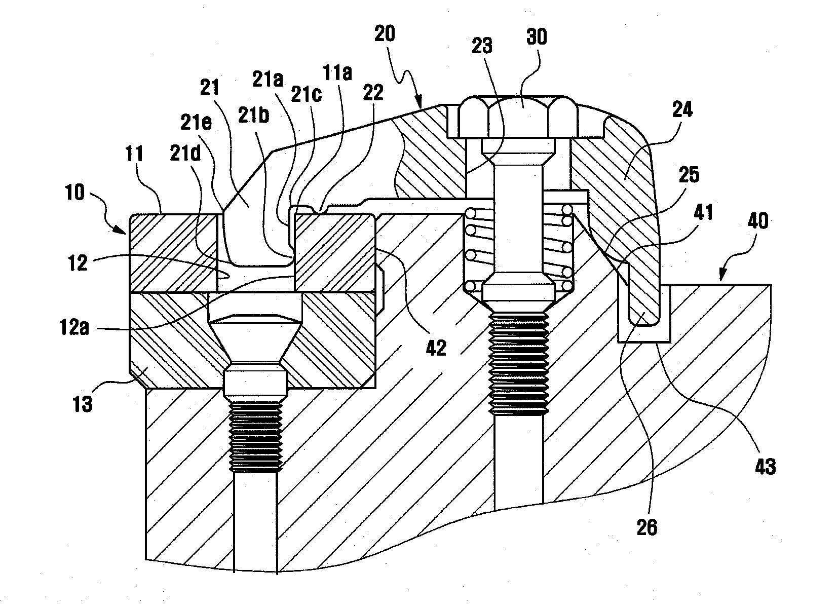
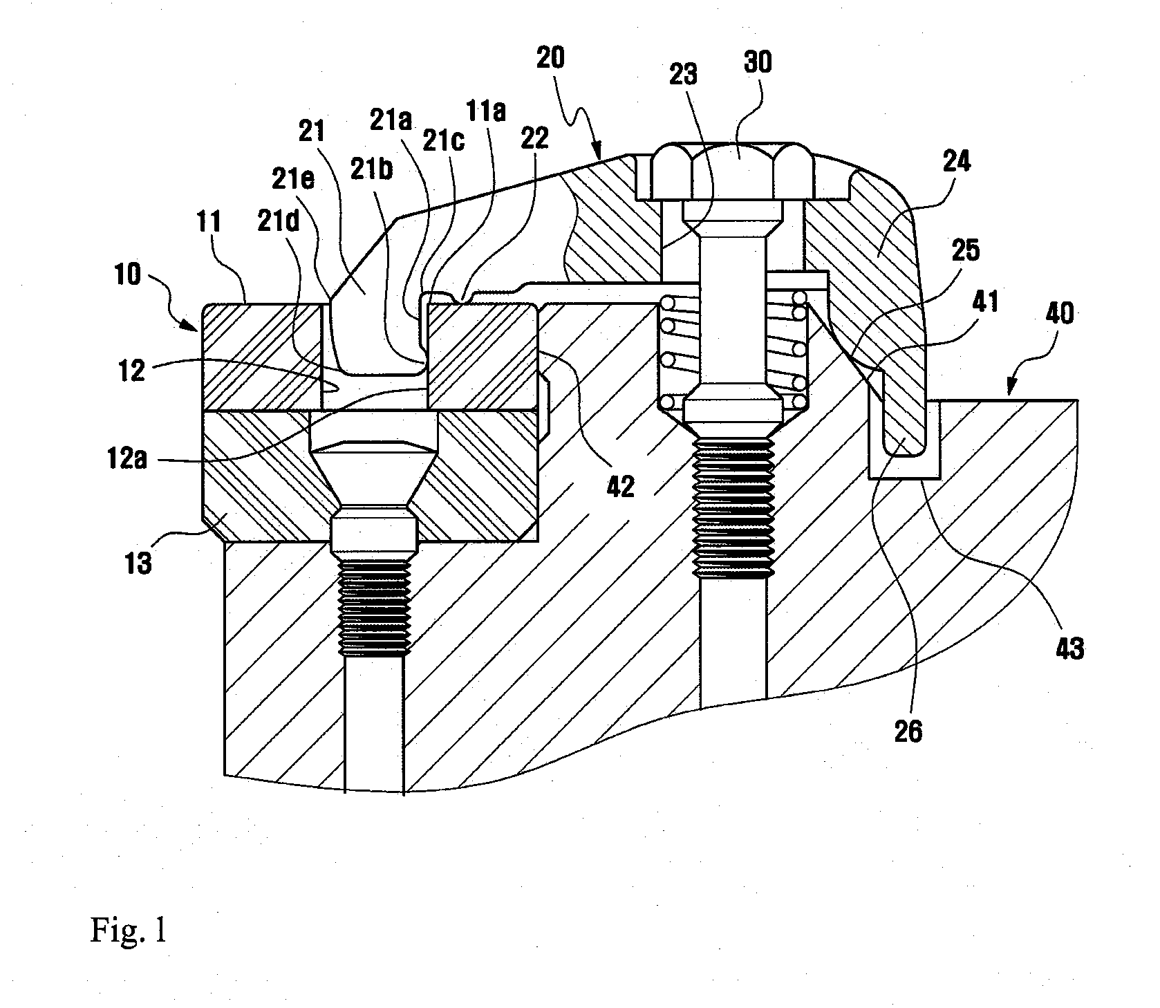
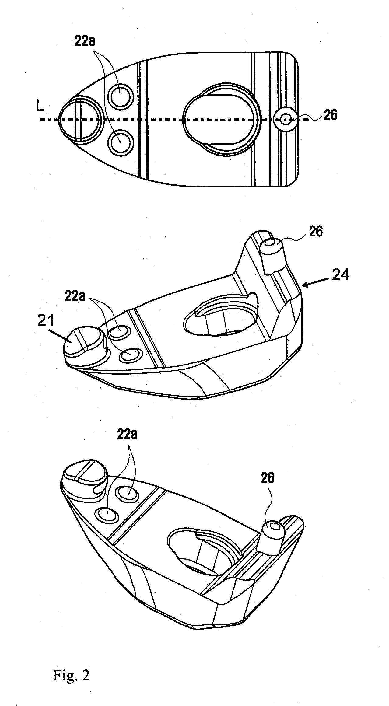
[0026]FIG. 1 is a sectional view depicting a tool holder assembly using an insert clamp in accordance with the present invention. And FIGS. 2 to 5 illustrate embodiments of the insert clamps in accordance with the present invention in plane or perspective views.

[0027]As shown in FIG. 1, the insert clamp 20 of the present invention is used to secure a cutting insert 10, which has a central hole 12 with its axis perpendicular to an upper surface 11, to a tool holder 40. The insert clamp 20 comprises a forward protrusion 21 to be received in the central hole 12 of the insert 10, a central body portion provided with a pressing part 22 to press down the upper surface 11 of the insert 10 and a screw hole 23 for a clamping screw 30 to pass through, and a rear protrusion 24 having a rear contact surface 25 to come in contact with a rearward slanting surface 41 of the tool holder 40.

[0028]The forward protrusion 21 is formed on the forward end of the insert clamp 20, an inside surface 21a of ...


PUM

PropertyMeasurementUnit
Lengthaaaaaaaaaa
Surface areaaaaaaaaaaa

Abstract

An insert clamp secures a cutting insert having a central hole to a tool holder. The clamp includes a forward protrusion to be received in the central hole of the insert, a central body portion provided with a pressing part to press down the upper surface of the insert and a screw hole for a clamping screw to pass through, and a rear protrusion having a rear contact surface to come in contact with a rearward slanting surface of the tool holder. The forward protrusion is formed on the forward end of the insert clamp, an inside surface of the forward protrusion extends downward in a spaced state apart from the inner wall of the central hole of the insert, and a distal portion of the inside surface the forward protrusion is provided with a protuberance of convex curved surface to come in tangential contact with the inner wall of the insert. The pressing part is formed on the bottom surface of the central body portion of the insert clamp, and has convex curved surfaces to come in tangential contact with the upper surface of the insert on both regions of the bottom surface of the central body portion which is bisected by a central line passing through the forward protrusion and the screw hole.

Description

TECHNICAL FIELD[0001]The present invention relates to a device clamping a cutting insert to a tool holder. A tool holder of this kind is particularly useful for an indexable insert with a central hole to be secured in a mounting seat of the tool holder.BACKGROUND ART[0002]An indexable inserts is mounted on a cutting tool holder for machining a workpiece and may take various shapes such as square and triangle with an equal corner angle all around the insert, or rhombic or rhomboidic shapes with acute nose point angles.[0003]In general, a machining tool mounted with this indexable insert is used for drilling, milling, and turning. In these various machining methods, the cutting insert is secured onto the seat of the tool holder by a clamping means and provides a cutting edge to contact the workpiece.[0004]A clamping means to secure an insert with a central hole to a tool holder has been disclosed in EP 0759826 B1. This clamping means intends to keep the insert in place in the pocket s...

Claims


Application Information

Patent Timeline
IPC IPC(8): B23B29/12
CPCB23B27/1677Y10T407/2274Y10T407/2272Y10T407/2276Y10T407/2282
Inventor PARK, HONG SIKCHO, HO-HYOUN
Owner TAEGUTEC
Learn More