
State of charge range

a lithium-ion battery, state-of-charge technology, applied in the direction of material electrochemical variables, hybrid vehicles, instruments, etc., can solve the problems of difficult to accurately ascertain battery capacity, serious repercussions, and technique that does not provide a very accurate assessment of battery capacity, so as to improve the cycle life of lithium-ion battery packs

Active Publication Date: 2011-06-30
TESLA INC
View PDF4 Cites 69 Cited by
  • Summary
  • Abstract
  • Description
  • Claims
  • Application Information

AI Technical Summary

Benefits of technology

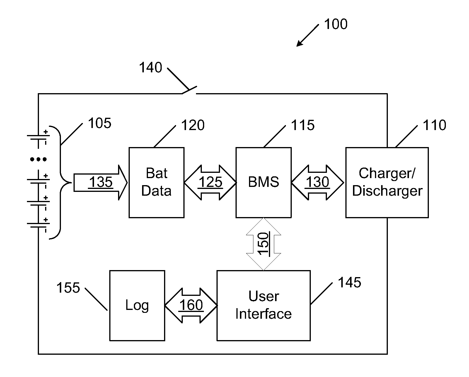
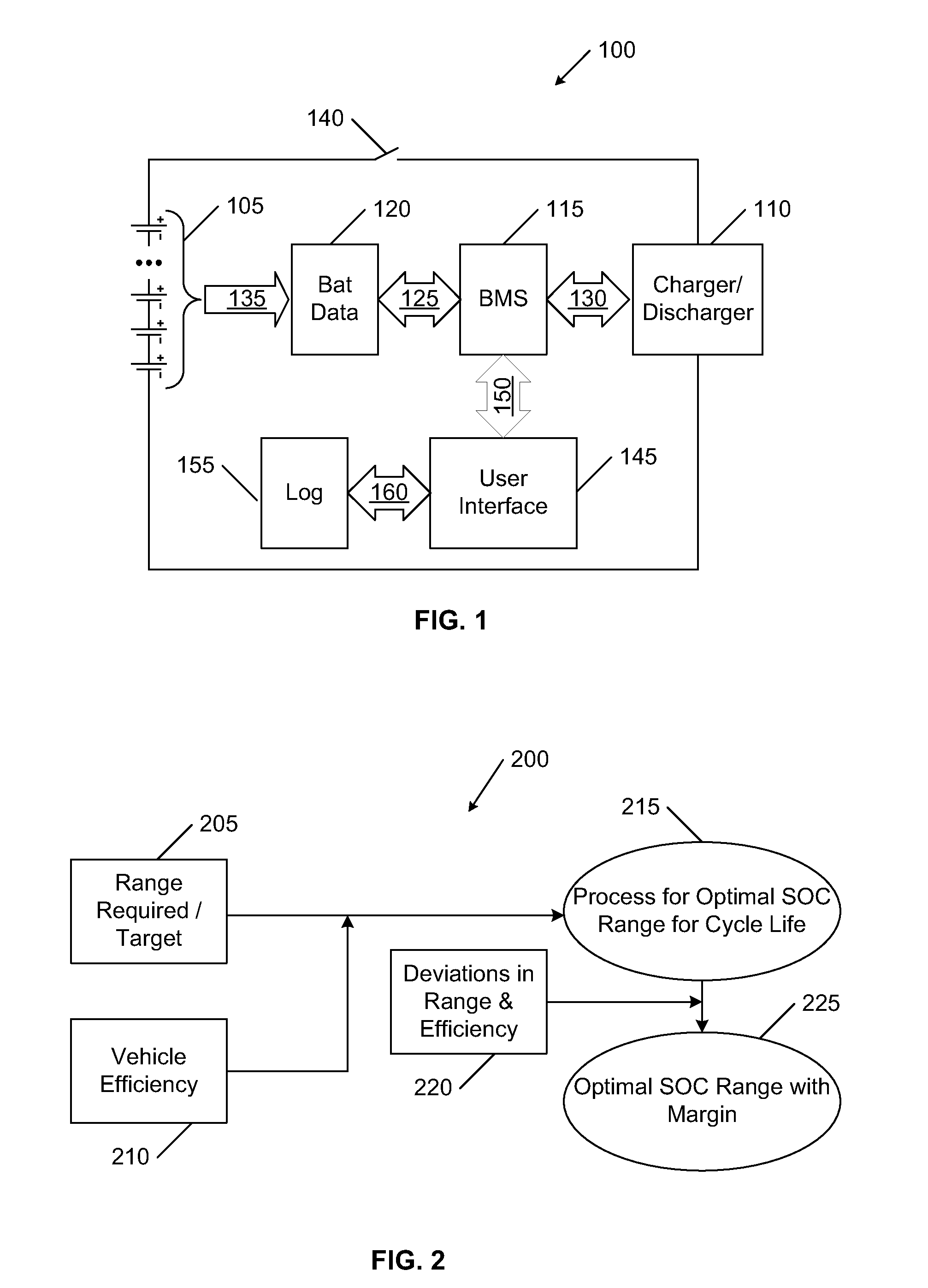
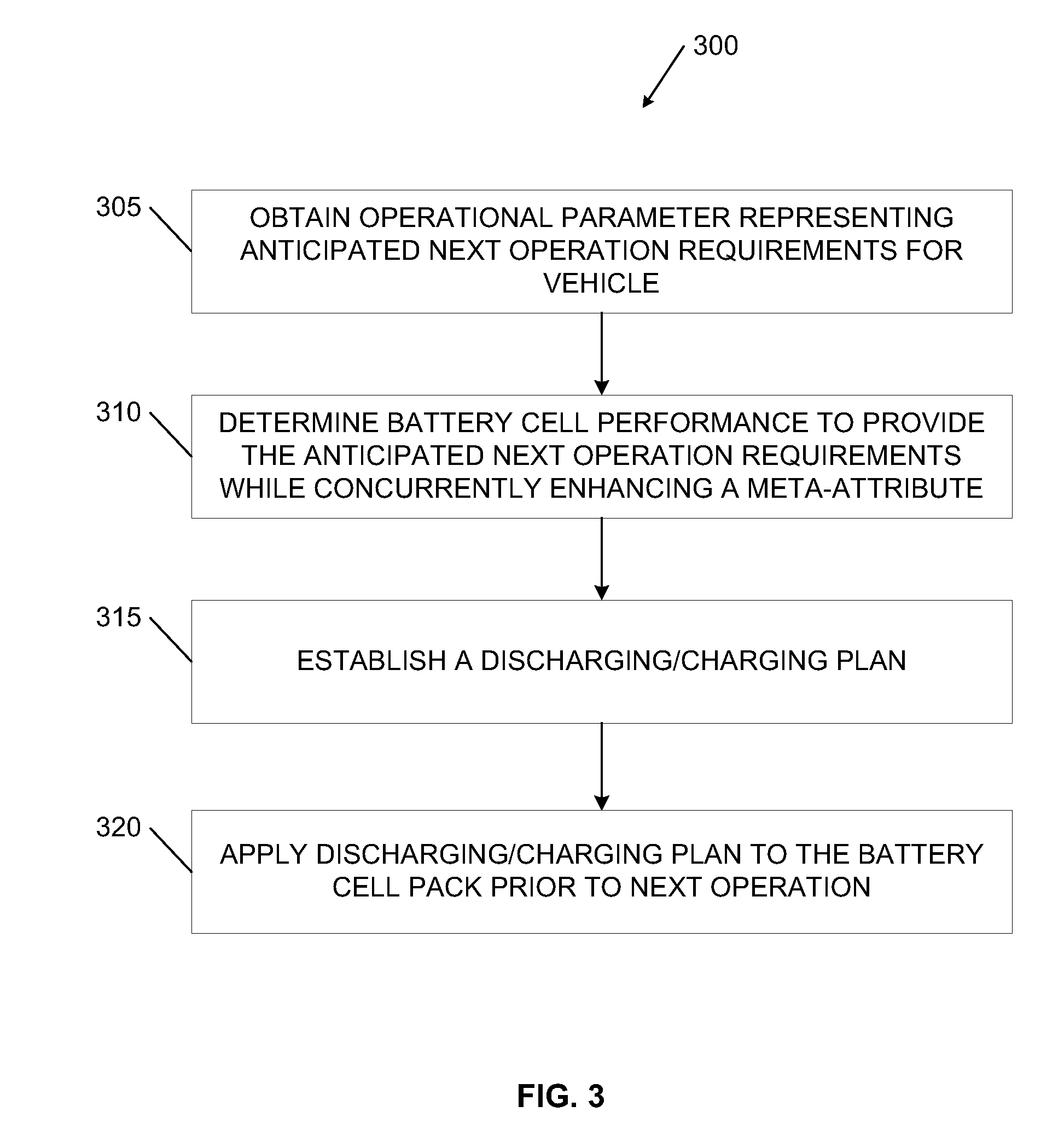
[0017]Disclosed is a system and method for improving cycle lifetimes for a lithium-ion battery pack, particularly for adapting to a dynamic use profile for a user. A management system for a battery cell pack, the management system has a controller determining an adjustable charge profile for the battery cell pack wherein the adjustable charge profile includes: an operational parameter identifying a next operation post-charge performance characteristic for the battery cell pack wherein a controller determines a next cycle plan for the battery cell pack that provides the performance characteristic while concurrently enhancing an attribute of the battery cell pack and wherein the attribute is measured over a plurality of applied cycles; and one or more charging stages to produce an energy ending point for the plan.

Problems solved by technology

Unfortunately, under normal use conditions such as those encountered in an electric vehicle or other battery-power device, it is difficult to accurately ascertain battery capacity.
Unfortunately this technique does not provide a very accurate assessment of battery capacity, both because some factors are not properly taken into account (e.g., historical temperature profiles, load conditions, depth of discharge prior to each charging, charge / discharge rates, etc.) and because the effects of the errors accumulate as the battery ages.
Although this technique can be used occasionally, using it on a routine basis can have serious repercussions since deep discharging a battery, and in particular fully discharging a battery, can dramatically shorten its lifetime.
Additionally, for most battery-powered devices, especially electric vehicles, it would be extremely inconvenient to require that the user allow the battery to become fully discharged prior to charging.
As battery packs used for heavy use, such as automotive electric vehicles and other heavy industrial application often have thousands of battery cells, and the assembly of the cells represents a large investment of resources (money and time), issues regarding safety and degradation are even more important.
This capacity loss manifests itself in increased internal resistance caused by mechanical stresses (e.g., volume change, side reactions and the like) and oxidation.
Eventually, the cell resistance reaches a point where the pack is unable to deliver the stored energy although the battery may still have ample charge.
High charge levels and elevated temperatures hasten permanent capacity loss.
High charge voltages, excessive charge rate and extreme load conditions will have a negative effect and shorten the battery life.
Not only is it better to charge lithium-ion battery at a slower charge rate, high discharge rates also contribute the extra wear and tear.
A moderate charge and discharge puts less stress on the battery, resulting in a longer cycle life.
Even though incremental improvements may be achieved with careful use of the battery, the battery cell environment and the services required are not always conducive to achieve optimal battery life.
The very considerations given above for increasing battery cycle life can often conflict with some of the requirements for long vehicle range and use of high performance battery packs used in automotive applications and other industrial scenarios.
The challenges are increased because each user will have different requirements, and those requirements will vary over time.
In short, there is typically not a single solution that can be established a priori for each user.

Method used


Image

  • State of charge range
  • State of charge range
  • State of charge range

Examples


Embodiment Construction

[0024]Embodiments of the present invention provide a system and method for a management system and a battery charger for improving cycle lifetimes for a battery cell pack, particularly for adapting to a dynamic use profile for a user of an electric vehicle. The following description is presented to enable one of ordinary skill in the art to make and use the invention and is provided in the context of a patent application and its requirements. In the following text, the terms “battery”, “cell”, “battery cell” and “battery cell pack” may be used interchangeably and may refer to any of a variety of different rechargeable cell chemistries and configurations including, but not limited to, lithium ion (e.g., lithium iron phosphate, lithium cobalt oxide, other lithium metal oxides, etc.), lithium ion polymer, nickel metal hydride, nickel cadmium, nickel hydrogen, nickel zinc, silver zinc, or other battery type / configuration. Various modifications to the preferred embodiment and the generic...


PUM

PropertyMeasurementUnit
energyaaaaaaaaaa
post-charge performanceaaaaaaaaaa
voltageaaaaaaaaaa

Abstract

A system and method for improving cycle lifetimes for a lithium-ion battery pack, particularly for adapting to a dynamic use profile for a user. A battery cell pack charging system, including a charger and a controller, for charging a lithium-ion battery cell pack, the battery cell pack charging system has a circuit for charging the battery cell pack using an adjustable charging system including an adjustable charge profile to charge the battery cell pack wherein the adjustable charge profile includes: an operational parameter identifying a next operation post-charge performance characteristic for the battery cell pack wherein a controller determines a next cycle plan for the battery cell pack that provides the performance characteristic while concurrently enhancing an attribute of the battery cell pack and wherein the attribute is measured over a plurality of applied cycles; and one or more charging stages to produce an energy ending point for the plan; wherein the adjustable charge plan is implemented by the charger in anticipation of a post-charging operation associated with the operational parameter.

Description

BACKGROUND OF THE INVENTION[0001]The present invention relates generally to rechargeable lithium-ion-type chemistry batteries, and more specifically to improving battery pack life of automotive Li-ion battery packs.[0002]Lithium ion batteries are common in consumer electronics. They are one of the most popular types of battery for portable electronics, with one of the best energy-to-weight ratios, no memory effect, and a slow loss of charge when not in use. In addition to uses for consumer electronics, lithium-ion batteries are growing in popularity for automotive, defense, and aerospace applications due to their high energy and power density.[0003]One of the advantages of use of a Li-ion chemistry is that batteries made using this technology are rechargeable. Traditional charging is done with a two-step charge algorithm: (i) constant current (CC), and (ii) constant voltage (CV). In electric vehicles (EVs), the first step could be constant power (CP).[0004]Step 1: Apply charging cur...

Claims


Application Information

Patent Timeline
Patent Type & Authority Applications(United States)
IPC IPC(8): H02J7/00G01N27/27
CPCH02J7/0073H02J7/0071
Inventor KISHIYAMA, CLAY H.MEHTA, VINEET H.GADDA, CHRISTOPHER D.
Owner TESLA INC
Learn More